Embedded electromechanical device state monitoring and fault diagnosis system

A technology for fault diagnosis system and electromechanical equipment, which is applied in the testing, measuring devices, instruments, etc. of machine/structural components, which can solve the problems of less multi-parameter monitoring, slow system response speed, power consumption and volume limitation, etc., to improve the integration degree and reliability, reducing the number of circuit boards, reducing the effect of system volume

Inactive Publication Date: 2017-06-16
重庆德秋建设工程有限公司
View PDF0 Cites 3 Cited by
  • Summary
  • Abstract
  • Description
  • Claims
  • Application Information

AI Technical Summary

Problems solved by technology

[0003] At present, many types of portable equipment operation status monitoring instruments have appeared, but most of these equipments only monitor a single parameter, and few of them can perform multi-parameter monitoring, and these equipment can only perform front-end data collection and waveform display, data analysis And diagnosis and other functions need to be realized by importing data into the computer
Moreover, most condition monitoring products are poor in portability, large in size, and heavy in weight, making them inconvenient to be used flexibly in industrial sites. Most of the equipment condition monitoring products with strong functions mostly use the Windows operating system. Although it is easy to program, the system overhead is large and the system slow response
Moreover, the general remote real-time monitoring system needs to configure a dedicated industrial computer on site for equipment status data collection and monitoring, which not only costs a lot, but also is limited by the site environment in terms of power consumption and volume

Method used


Image

  • Embedded electromechanical device state monitoring and fault diagnosis system
  • Embedded electromechanical device state monitoring and fault diagnosis system
  • Embedded electromechanical device state monitoring and fault diagnosis system

Examples


Embodiment Construction

[0019] The present invention will be described in detail below in conjunction with the accompanying drawings and embodiments.

[0020] The present invention combines RISC (reduced instruction set computer) processor, FPGA (programmable logic controller) and embedded operating system Windows CE to provide an embedded movable equipment state monitoring and fault diagnosis system.

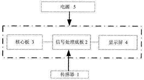
[0021] Such as figure 1 As shown, the present invention includes a sensor 1 , a signal processing backplane 2 , a core board 3 , a touch-type liquid crystal display 4 and a power supply 5 . The sensor 1 inputs all the collected signals into the signal processing base board 2, and the signal processing base board 2 is plugged into the core board 3, and the core board 3 controls the signal processing base board 2 to perform pre-amplification, selection, filtering, data acquisition and monitoring of all signals. Data communication and other processing. The signal processing backplane 2 displays the...


PUM


Abstract

The invention relates to an embedded electromechanical device state monitoring and fault diagnosis system comprising a sensor, a signal processing bottom board, a core board, a liquid crystal touch type display screen, and a power supply. The sensor inputs a collected signal into the signal processing bottom board plugged with the core board; and the core board controls the signal processing bottom board to carry out pre processing, data acquisition, and data communication processing on all signals. The signal processing bottom board enables the information of the processed signal to be displayed in real time in an on-line mode by a display screen connected with the signal processing bottom board. Power of the signal processing bottom board, the core board, and the display screen are provided by the power supply. According to the system provided by the invention, because the embedded computer core board controls the signal processing bottom board to carry out pre processing, data acquisition, and data communication processing on tested signals and the core board and the signal processing bottom board are connected in a plugging manner, the circuit board number is reduced and the system integration and reliability are improved. The system can be applied to monitoring of various electromechanical device states widely.

Description

technical field [0001] The invention relates to an embedded and test analysis system, in particular to an embedded electromechanical equipment state monitoring and fault diagnosis system. Background technique [0002] Rotating machinery is widely used in industrial production, and many of them occupy an important position in production. In order to meet production needs, these devices are generally in continuous operation. If these devices fail, it will not only cause major accidents, but also seriously affect production and cause major economic losses. Therefore, ensuring their safe and stable operation is the key to ensuring production. key. At present, most large-scale key rotating machinery have installed online and remote condition monitoring and fault diagnosis systems, but many small and medium-sized equipment are only equipped with very simple monitoring equipment, and only monitor some routine parameters. These small and medium-sized equipment also have Many of ...

Claims


Application Information

Patent Timeline
IPC IPC(8): G01M99/00
Inventor 陈德张可新陈光国
Owner 重庆德秋建设工程有限公司
Why Eureka
Try Eureka