
Tapping method for pipeline arc surface and cutting torch support adjusting device for tapping

A technology of adjusting device and curved surface, applied in welding equipment, gas flame welding equipment, metal processing equipment, etc., can solve the problems of irregular opening shape, dense distribution, heavy workload, etc., to improve cutting accuracy and simple operation , The effect of easy disassembly and assembly

Active Publication Date: 2017-06-20
CHINA NUCLEAR IND FIFTH CONSTR CO LTD
View PDF5 Cites 8 Cited by
  • Summary
  • Abstract
  • Description
  • Claims
  • Application Information

AI Technical Summary

Problems solved by technology

However, when using a waterjet machine tool to cut and form the installation hole of the pipe platform, since the reserved space on the pipe installation site is not enough to place the waterjet machine tool, it is necessary to transport the holed pipe to the waterjet machine room to complete the cutting work, and then transport it to the waterjet machine room. Go back to the pipeline installation site to install the pipe platform, and transfer the perforated pipeline back and forth. The workload is large, time-consuming and laborious, which leads to low perforation efficiency and high perforation cost; when manual perforation is used, due to the large perforation size, the perforation position Dense distribution, irregular opening shape, and unstable manual operation, resulting in difficulty in manual opening, low opening efficiency, low opening accuracy, and difficult to meet the installation requirements of the pipe platform

Method used


Image

  • Tapping method for pipeline arc surface and cutting torch support adjusting device for tapping
  • Tapping method for pipeline arc surface and cutting torch support adjusting device for tapping
  • Tapping method for pipeline arc surface and cutting torch support adjusting device for tapping

Examples


Embodiment Construction

[0032] Below, combine Figure 1-8 The method for opening holes on the curved surface of pipelines and the cutting torch support adjustment device for opening holes of the present invention will be described in detail.

[0033] The method for opening holes on the curved surface of the pipeline of the present invention comprises the following steps:

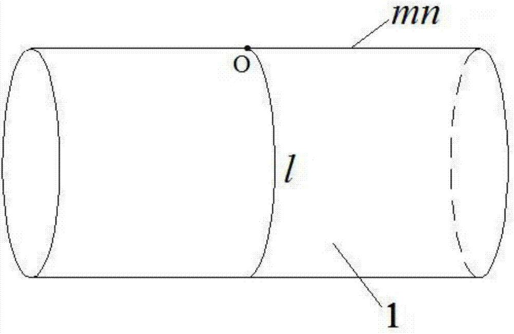
[0034] Step S1, according to the designed opening position, use a measuring ruler to measure the distance between the end surface of the perforated pipeline 1 and the center point O of the perforated pipeline on the outer surface of the perforated pipeline 1, so that Mark the position of the center point O of the opening, such as figure 1 As shown, and on the outer surface of the perforated pipeline 1, the axial positioning line mn and the circumferential positioning line l passing through the center point O of the perforated pipe are drawn.

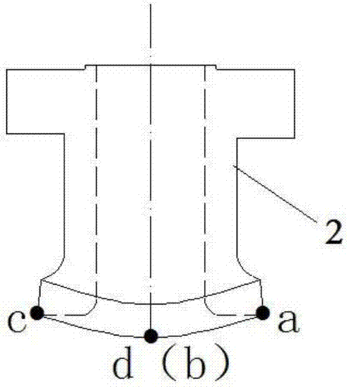
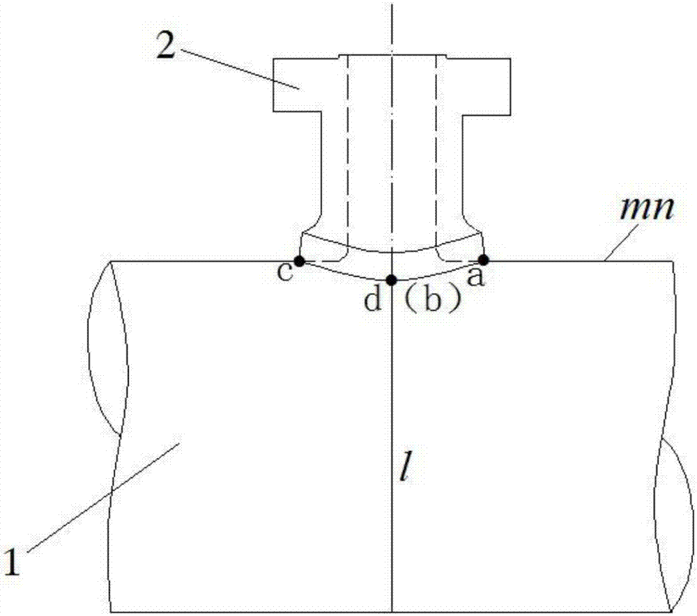
[0035] Step S2, in such as figure 2 Four positioning points a, b, c and d are marked ...


PUM


Abstract

The invention relates to the field of pipeline tapping. In order to improve tapping efficiency and tapping precision, the invention provides a tapping method for a pipeline arc surface. The method comprises drawing an axial positioning line, a peripheral positioning line, a profile line of a pipe platform mounting hole and a cutting line; setting cutting-starting points A' and B' and pre-stopping points C and D; mounting a cutting torch support adjusting device comprising a rotary shaft, an adjusting vertical rod and an adjusting cross rod on a tapping pipeline, and sleeving a fixing sleeve on the lower end of the rotary shaft and vertically fixing on the tapping pipeline; adjusting the cutting torch support adjusting device and starting cutting torque for preheating till a preheated region is in a range of 150-250 DEG C, and closing the cutting torch; adjusting the cutting torch support adjusting device, cutting from the cutting-starting points A' and B' to the pre-stopping points C and D along the cutting line, and closing the cutting torch; detaching the cutting torch support adjusting device, and handholding the cutting torch to cut the rest part along the cutting line till cutting is finished. By adopting such tapping method for a pipeline arc surface to tap the pipeline arc surface, the tapping efficiency and tapping precision are high and operation is simple and convenient.

Description

technical field [0001] The invention relates to the field of drilling holes on arc surfaces, in particular to a method for drilling holes on the arc surface of pipelines and a cutting torch support adjustment device used in drilling. Background technique [0002] In the nuclear power, petroleum and chemical industries, especially in the construction of nuclear power plants, it is often necessary to drill holes for pipelines. For example, during the construction and installation process of the AP1000 nuclear power plant, when it is necessary to install pipe platforms with diameters of 6", 8" and 12" on the main steam pipeline with a diameter of 38", it is necessary to set up diameters on the main steam pipeline. 16″, 13.9″, 25″ pipe platform installation holes. At present, water cutting machine tools are often used to cut the perforated pipes in the water cutting machine room to form pipe platform installation holes, or the opening personnel hold cutting tools at the pipeline...

Claims


Application Information

Patent Timeline
IPC IPC(8): B23K7/00B23K7/10
CPCB23K7/006B23K7/102B23K7/105
Inventor 王兴华赵国鑫武建勇陈虹睿丁超丁军凯李勇
Owner CHINA NUCLEAR IND FIFTH CONSTR CO LTD
Learn More