
Electrolytic refining system and method for crude copper with high precious metal content

An electrolytic refining and precious metal technology, applied in the electrolytic process, electrolytic components, electrodes, etc., can solve the problems of affecting the quality of the cathode copper plate, easily falling to the cathode copper plate, and precious metal loss.

Active Publication Date: 2017-06-20
包小玲
View PDF10 Cites 3 Cited by
  • Summary
  • Abstract
  • Description
  • Claims
  • Application Information

AI Technical Summary

Problems solved by technology

Due to the relatively high content, it is easy to fall on the cathode copper plate
Causes precious metal loss and affects the quality of the cathode copper plate

Method used


Image

  • Electrolytic refining system and method for crude copper with high precious metal content
  • Electrolytic refining system and method for crude copper with high precious metal content

Examples


Embodiment 1

[0031] A blister copper electrolytic refining system with high precious metal content, comprising:

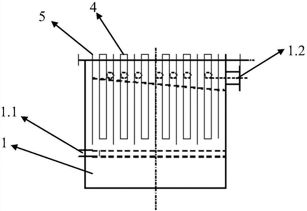
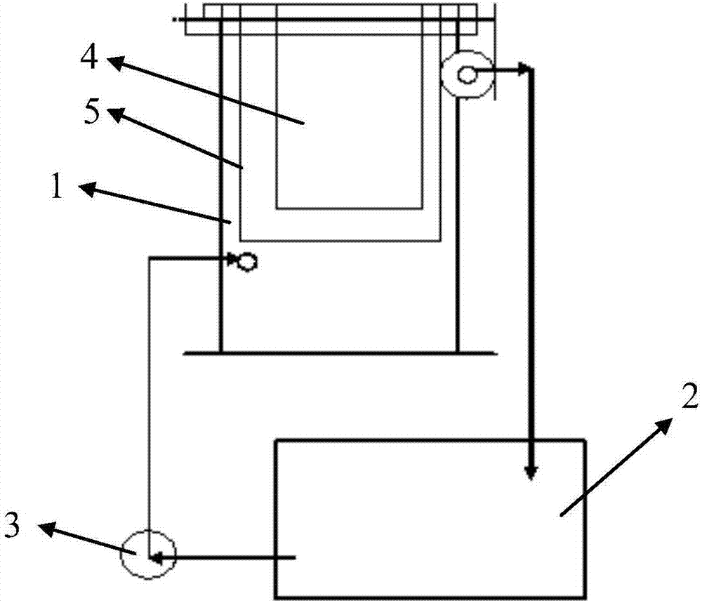
[0032] An electrolytic cell 1 for containing industrial electrolyte, a liquid inlet 1.1 is provided below the electrolytic cell 1, an overflow port 1.2 is provided above the electrolytic cell 1, and the liquid inlet 1.1 and the overflow port 1.2 are set opposite to the electrolytic cell 1 On the two side walls of the tank, the industrial electrolyte flows into the electrolytic cell 1 through the liquid inlet 1.1, and flows out of the electrolytic cell through the overflow port 1.2.

[0033] The electrolyte lower tank 2 is located below the electrolytic tank 1 and communicates with the liquid inlet 1.1 and the overflow port 1.2 of the electrolytic tank respectively, and a circulation pump 3 is provided between the lower electrolyte tank 2 and the liquid inlet 1.1 of the electrolytic tank, The circulating pump 3 is used to directly pump the electrolyte in the electrolyte lower ta...

Embodiment 2

[0038] A blister copper electrolytic refining method with high precious metal content, the blister copper to be refined is set as at least one anode, the anode is in contact with the electrolyte, and an anode bag is provided outside the anode; at least one cathode is in contact with the electrolyte, and the anode It is set in the same electrolytic cell as the cathode. There is a liquid inlet below the electrolytic cell and an overflow port above the electrolytic cell. The liquid inlet and overflow are set on the two opposite side walls of the electrolytic cell. Industrial The electrolyte flows into the electrolytic cell from the liquid inlet, and flows out of the electrolytic cell from the overflow port. There is a circulating pump between the liquid inlets of the tank, which is used to pump the electrolyte in the lower tank of the electrolyte directly into the electrolytic tank, and the current density during the electrolysis process is 600-1000A / m 2 , The electrolyte in the ...


PUM


Abstract

The invention discloses an electrolytic refining system and method for crude copper with the high precious metal content. The system comprises an electrolytic cell used for containing an industrial electrolyte, an electrolyte low tank, at least one anode and at least one cathode. The anodes are formed by to-be-refined crude copper materials and are positioned to be used for making contact with the industrial electrolyte in the electrolytic cell, the peripheries of the anodes are sleeved with anode bags, and the anodes are wrapped inside the anode bags. The cathodes are positioned to be used for making contact with the industrial electrolyte in the electrolytic cell. The anodes are opposite to the cathodes, and the opening direction of a liquid inlet and the opening direction of an overflow opening are parallel to the fixing direction of the cathodes and the anodes. According to the system, a high tank of a common copper electrolytic technology is removed, the circulation speed of the electrolyte in the cell is increased, the production and operation period of precious metal recycling is shortened by the adoption of the system, and the losses of precious metal in the high-speed copper electrolytic production process are reduced.

Description

technical field [0001] The invention relates to a blister copper electrolysis process. Background technique [0002] It is a relatively mature process to purify blister copper and recover the rare and precious metals contained in it by electrolytic refining process. However, unlike mineral blister copper, the blister copper produced by the waste circuit board recycling industry and the blister copper produced by using copper as a collector for precious metal smelting contains much higher levels of rare and precious metals such as gold, silver, and platinum. Rare and precious metal contained in mineral blister copper. Therefore, new electrolytic processes should be developed to adapt to the characteristics of the industry. Otherwise, it will cause more valuable metals to take up more pressure and cause more losses. [0003] In the prior art, generally, blister copper is fused and cast into an anode, a pure copper plate (or titanium plate, stainless steel plate) is used as ...

Claims


Application Information

Patent Timeline
IPC IPC(8): C25C1/12C25C1/20C25C7/02C25C7/06
CPCC25C1/12C25C1/20C25C7/02C25C7/06Y02P10/20
Inventor 包小玲宋纲峰王德雨刘学山
Owner 包小玲
Learn More