Al technical title is built by PatSnap Al team. It summarizes the technical point description of the patent document.
An engine and high-speed technology, applied in the direction of machines/engines, non-variable engines, mechanical equipment, etc., can solve the problems of no labor-saving transmission structure, damage to the natural environment, and non-concentrated thrust, and achieve huge commercial development value and easy Manufacturing, low cost effect
Pending Publication Date: 2017-06-20
夏建国
View PDF0 Cites 1 Cited by
Summary
Abstract
Description
Claims
Application Information
AI Technical Summary
This helps you quickly interpret patents by identifying the three key elements:
Problems solved by technology
Method used
Benefits of technology
Problems solved by technology
[0002] The steam engines that appear on the market are all turbofan or crankshaft-type steam engines. They do not have a labor-saving speed changer structure, which is not labor-saving, energy-saving (steam), and difficult to manufacture. Propelling the turbofan to rotate consumes a huge amount of steam (energy), and the steam efficiency is only about 50%, which is low in efficiency and wastes a huge amount of energy. However, when the crankshaft type steam engine piston does work, the thrust is not concentrated, and the piston pushes the connecting rod in a straight line. When the rod pushes the crankshaft, the thrust turns outward, and a lot of power is lost. They are not labor-saving, energy-saving, difficult to manufacture, consume huge energy, and also produce huge carbon dioxide and harmful gases, which damage the natural environment. Now fossil energy is increasingly Exhaustion, energy shortage, and high oil prices, only vigorously create new energy-saving equipment, save energy, and protect the natural environment. This is the last word
Method used
Image
Click on the blue label to locate the original text in one second.
Reading with bidirectional positioning of images and text.
Examples
Embodiment Construction
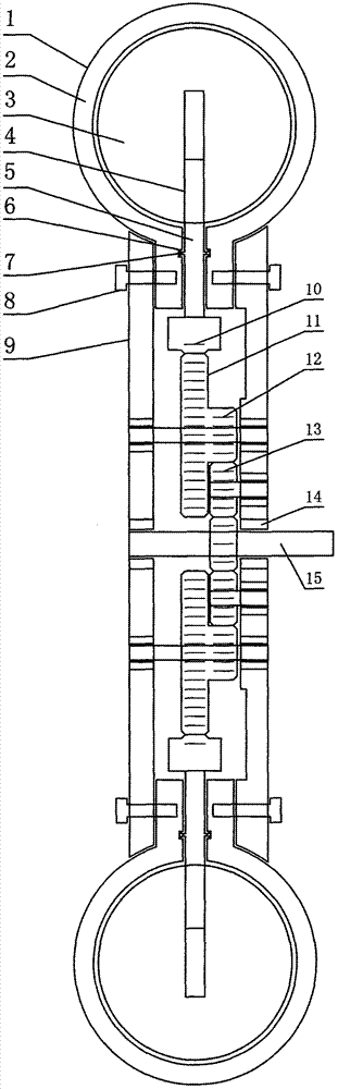
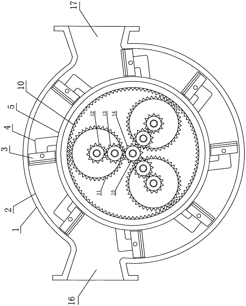
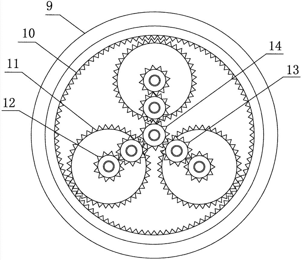
[0011] Such as figure 1 , 2 , Shown in 3: a piston-wheel type high-speed labor-saving steam engine, which includes a housing 1, an annular cylinder 2, a piston 3, a lever 4, a sealing ring 5, a concave groove 6, an inflatable sealing ring 7, and a screw nut 8. Sealing cover 9, ring gear 10, lever gear 11, 12, connecting gear 13, main shaft gear 14, bearing 15, air inlet 16, exhaust port 17, steam pipe, valve, computer, wire, instrumentation and electronics The switch, the ring gear 10 and the sealing ring 5 are integrated, and have the function of a flywheel. The ring gear 10 is matched with the lever gear large gear 11. The combination of the ring gear 10, the lever gears 11, 12, the connecting gear 13 and the main shaft gear 14 is labor-saving Speed changer, it has the function of labor saving, energy saving and speed change, the diameter of ring gear 10 is 2 times or 3 times of the diameter of lever gear bull gear 11, lever gear 11, 12 is made up of bull gear 11 and pini...
PUM
Abstract
The present invention is a piston-wheel type high-speed labor-saving steam engine without turbine and crankshaft, which completely changes the structure of the existing steam engine. It includes a shell, an annular cylinder, a piston, a lever, a sealing ring, a sealing cover, a ring gear, Lever gears, connecting gears, main shaft gears, bearings, air inlets, exhaust ports, steam pipes, valves, computers, wires, instruments and meters, and electronic switches, computer control during startup, steam enters from the air inlet, and exhaust gas from the exhaust Outlet, when the valve is opened for air intake, the steam pushes the piston, the piston pushes the lever, the lever pushes the seal ring and the ring gear to rotate, the ring gear rotates to drive the lever gear to rotate, and the lever gear rotates to drive the connecting gear and the main shaft gear to run together at high speed. Novel, strong practicability, simpler structure, more scientific, easier to manufacture, lower energy consumption, greater power, faster speed, less noise, lower cost, wide application, and huge commercial development value. The world's most labor-saving and energy-saving, the most advanced high-speed labor-saving steam engine.
Description
technical field [0001] The invention relates to a piston-wheel type high-speed labor-saving steam engine. Background technique [0002] The steam engines that appear on the market are all turbofan or crankshaft-type steam engines. They do not have a labor-saving speed changer structure, which is not labor-saving, energy-saving (steam), and difficult to manufacture. Propelling the turbofan to rotate consumes a huge amount of steam (energy), and the steam efficiency is only about 50%, which is low in efficiency and wastes a huge amount of energy. However, when the crankshaft type steam engine piston does work, the thrust is not concentrated, and the piston pushes the connecting rod in a straight line. When the rod pushes the crankshaft, the thrust turns outward, and a lot of power is lost. They are not labor-saving, energy-saving, difficult to manufacture, consume huge energy, and also produce huge carbon dioxide and harmful gases, which damage the natural environment. Now fos...
Claims
Application Information
Patent Timeline
Application Date:The date an application was filed.
Publication Date:The date a patent or application was officially published.
First Publication Date:The earliest publication date of a patent with the same application number.
Issue Date:Publication date of the patent grant document.
PCT Entry Date:The Entry date of PCT National Phase.
Estimated Expiry Date:The statutory expiry date of a patent right according to the Patent Law, and it is the longest term of protection that the patent right can achieve without the termination of the patent right due to other reasons(Term extension factor has been taken into account ).
Invalid Date:Actual expiry date is based on effective date or publication date of legal transaction data of invalid patent.