Device system utilizing cement plant waste heat for achieving carbon dioxide cyclic power generation

A cement plant, waste heat technology, applied in the equipment system field of carbon dioxide cycle power generation, can solve problems such as inappropriate

Active Publication Date: 2017-06-20
长沙紫宸科技开发有限公司
View PDF7 Cites 5 Cited by
  • Summary
  • Abstract
  • Description
  • Claims
  • Application Information

AI Technical Summary

Problems solved by technology

Obviously, the existing CO 2 Cycle power generation technology is not suitable for the cement industry in my country

Method used


Image

  • Device system utilizing cement plant waste heat for achieving carbon dioxide cyclic power generation
  • Device system utilizing cement plant waste heat for achieving carbon dioxide cyclic power generation
  • Device system utilizing cement plant waste heat for achieving carbon dioxide cyclic power generation

Examples


Embodiment 1

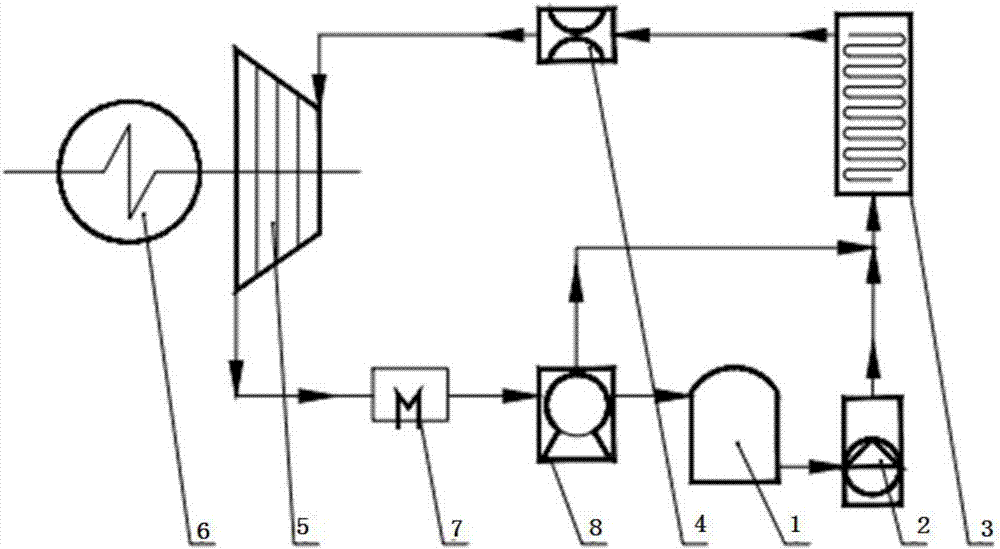
[0053] Such as figure 1 As shown, the present invention provides an equipment system for utilizing the waste heat of a cement plant to realize carbon dioxide cycle power generation, mainly including liquid CO 2 Storage tank 1, high pressure pumping device 2, CO 2 Energy storage device 3, flow stabilizer 4, turbine / piston expander 5, generator 6, cooling device 7, compression device 8, the liquid CO 2 The outlet of the storage tank 1 is connected with the inlet of the high-pressure pumping device 2, and the outlet of the high-pressure pumping device 2 is connected with the CO 2 The inlet of energy storage device 3 is connected, CO 2 The outlet of the energy storage device 3 is connected to the inlet of the flow stabilizer 4, the outlet of the flow stabilizer 4 is connected to the inlet of the turbine / piston expander 5, the turbine / piston expander 5 is connected to the generator 6 shaft, and the turbine / The outlet of the piston expander 5 is connected with the inlet of the ...

Embodiment 2

[0059] Such as Figure 4 As shown, the difference between Embodiment 2 and Embodiment 1 is that it also includes a regenerator 9; the outlet of the turbine / piston expander 5 communicates with the low-pressure fluid inlet of the regenerator 9, and the low-pressure fluid inlet of the regenerator 9 The fluid outlet is connected to the inlet of the cooling device 7, the outlet of the cooling device 7 is connected to the inlet of the compression device 8, and the outlet of the compression device 8 is respectively connected to the high-pressure fluid inlet of the regenerator 9, the CO 2 Inlet of energy storage device 3, liquid CO 2 The inlet of storage tank 1 is connected. After the turbine or piston expander 5 works and releases energy, low-pressure CO is discharged. 2 Fluid, low pressure CO 2 After the fluid recovers the waste heat through the regenerator 9, it is cooled by the cooling device 7, compressed by the compression device 8 and sent to liquid CO 2 The fluid in the st...

Embodiment 3

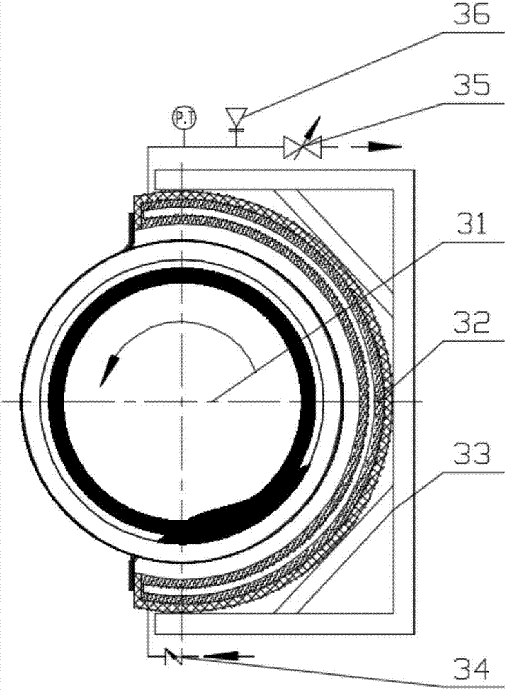
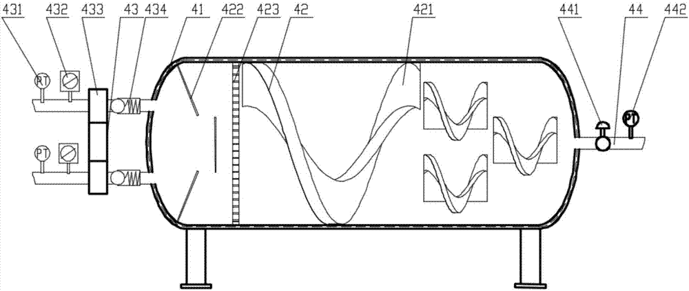
[0061] Such as Figure 5 As shown, the difference between Example 3 and Example 1 is that the CO 2 Energy storage device 3 is built-in CO for the kiln hood 2 The energy storage device 3a and the high temperature section of the kiln shell radiate CO 2 Combination of energy storage device 3b, built-in CO in the kiln hood 2 The energy storage device 3a and the high temperature section of the kiln shell radiate CO 2 The specific structure of energy storage device 3b can refer to Figure 4 , according to the specific device body, the structure of the device body changes, but the components in the device remain unchanged; wherein, the outlet of the high-pressure pumping device 2 is connected to the built-in CO of the kiln head cover respectively. 2 The inlet of the energy storage device 3a and the high temperature section of the kiln shell radiate CO 2 The inlet of the energy storage device 3b is connected, and the kiln head cover is built with CO 2 The outlet of the energy st...


PUM


Abstract

The invention provides a device system utilizing cement plant waste heat for achieving carbon dioxide cyclic power generation. The device comprises a liquid CO2 storage tank, a high-pressure pumping device, a CO2 energy storage device, a flow stabilizer, a turbine/piston expander, a power generator, a cooling device and a compression device. The CO2 energy storage device is used for making low-pressure liquid CO2 fluid pumped out of the liquid CO2 storage tank directly absorb abandoned waste heat or high-temperature heat energy which is different in temperature and is produced by a cement production line for energy storage, and the low-pressure liquid CO2 fluid is converted into supercritical CO2 fluid different in temperature, pressure and energy density. The flow stabilizer is used for converting the supercritical CO2 fluid different in temperature, pressure and energy density into equal-pressure supercritical CO2 fluid. According to the device system, captured carbon dioxide serves as a working medium, various kinds of abandoned waste heat which is generated in the cement production process and is large in temperature fluctuation and temperature difference is utilized as main energy to achieve carbon dioxide cyclic power generation, and energy consumption is low.

Description

technical field [0001] The invention relates to the technical field of low-carbon and energy utilization equipment, in particular to an equipment system for utilizing waste heat from a cement plant to realize carbon dioxide cycle power generation. Background technique [0002] Climate change has become one of the issues affecting human survival and development, and carbon dioxide emitted by industry is considered to be the main cause of climate warming. As the largest developing country in the world, our country uses coal as its primary energy and thermal power as its secondary energy as its energy structure. With the rapid growth of economic aggregate, the CO of primary energy and secondary energy 2 Emissions have the characteristics of fast growth and large total amount, but the current economical CCS or CCUS technology options for carbon emission reduction and climate change are limited, mainly concentrated in coal chemical industry, syngas and coal gasification-gas-stea...

Claims


Application Information

Patent Timeline
Patent Type & Authority Applications(China)
IPC IPC(8): F01K25/10F27D17/00
CPCF01K25/103F27D17/004F27D2017/007
Inventor 尹小林
Owner 长沙紫宸科技开发有限公司
Why Eureka
Try Eureka