Combined type tail water power generation set

A generator set and combined technology, applied in the direction of hydroelectric power generation, reaction engines, engine components, etc., can solve the problems of simple structure, waste of tail water, and unstable operation, etc., achieve freedom and convenience in use, increase power generation efficiency, The effect of improving power generation efficiency

Pending Publication Date: 2017-06-20
天津市创维机械设备制造有限公司
View PDF9 Cites 0 Cited by
  • Summary
  • Abstract
  • Description
  • Claims
  • Application Information

AI Technical Summary

Problems solved by technology

[0002] Hydropower generation is valued and vigorously developed by various countries for its advantages of no pollution, cleanliness and environmental protection. At the moment when energy is increasingly in short supply, hydropower generation is particularly important. The tail water is wasted in vain, and the utilization of tail water is paid more and more attention by people. Most of the existing tail water power generation devices are simple in structure, the utilization rate of tail water is not high, and the operation is not stable enough, as published in Chinese patent CN 201013525Y A tail water power generation device of a hydropower station, although it can utilize the tail water, but the design structure is simple, and the utilization rate of the tail water is not high
In some hydropower stations, the width of the river channel in the tailwater stage is not fixed, or the area with a small drop below it is not suitable for large-scale hydropower generation. However, the current tailwater generators are all fixed and not flexible enough to use

Method used


Image

  • Combined type tail water power generation set
  • Combined type tail water power generation set

Examples


Embodiment Construction

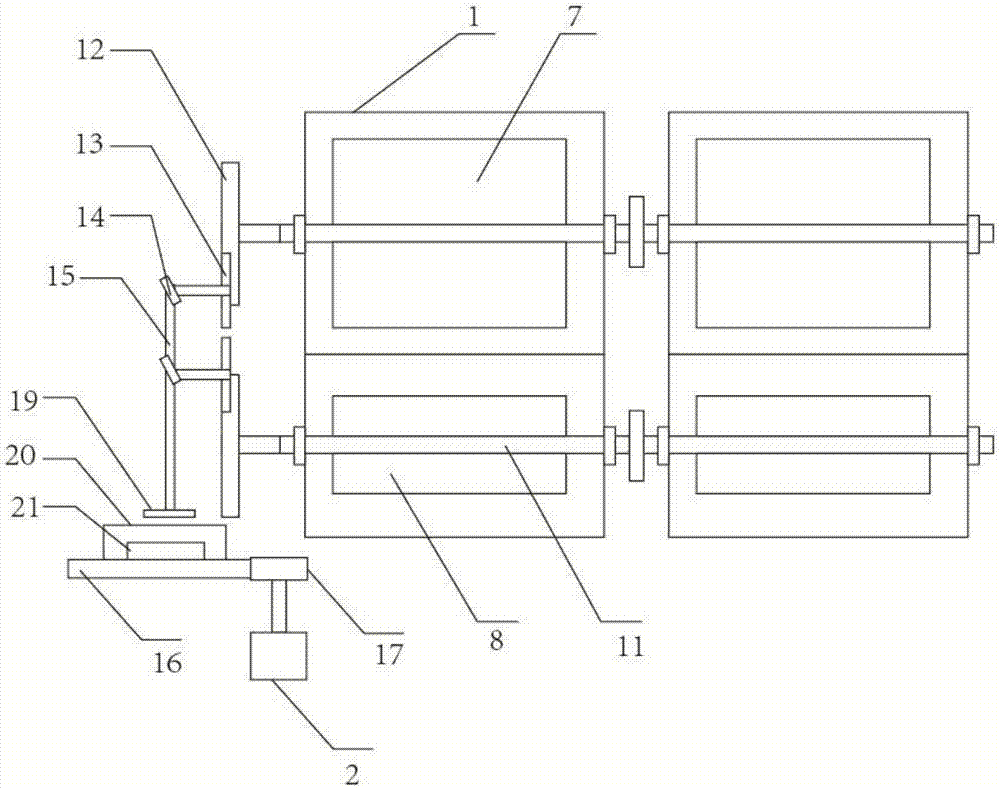
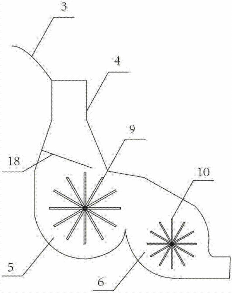
[0022] The technical solutions of the present invention will be clearly and completely described below in conjunction with the accompanying drawings. Apparently, the described embodiments are some of the embodiments of the present invention, but not all of them. Based on the embodiments of the present invention, all other embodiments obtained by persons of ordinary skill in the art without making creative efforts belong to the protection scope of the present invention.

[0023] In the description of the present invention, it should be noted that the terms "center", "upper", "lower", "left", "right", "vertical", "horizontal", "inner", "outer" etc. The indicated orientation or positional relationship is based on the orientation or positional relationship shown in the drawings, and is only for the convenience of describing the present invention and simplifying the description, rather than indicating or implying that the referred device or element must have a specific orientation, ...


PUM


Abstract

The invention discloses a combined type tail water power generation set. The combined type tail water power generation set is characterized by comprising a plurality of tail water turbines arranged in parallel and a generator; each tail water turbine comprises a water retaining plate, a water turbine shell body and water turbine bodies; each water turbine shell body comprises two chambers, that is, the first water turbine chamber and the second water turbine chamber, the bottoms of the first water turbine chamber and the second water turbine chamber are in circular arc shapes, the middles of the first water turbine chamber and the second water turbine chamber are provided with the first water turbine body and the second water turbine body, and the inner diameter of the first water turbine chamber is larger than that of the second water turbine chamber; the included angle between first water turbine blades and a blade bracket is 10-45 degrees; each second water turbine body comprises a plurality of second water turbine blades, and the included angle between the second water turbine blades and a blade bracket is 10-45 degrees; and each water turbine rotating shaft is connected with the generator through a driven gear and a speed increasing mechanism. According to the combined type tail water power generation set, the tail water turbines can be arranged and combined at random according to the widths of river channels, using is free and convenient, and in addition, the tail water power generation efficiency is improved.

Description

technical field [0001] The invention relates to the field of tail water power generation equipment, in particular to a combined tail water power generating set. Background technique [0002] Hydropower generation is valued and vigorously developed by various countries for its advantages of no pollution, cleanliness and environmental protection. At the moment when energy is increasingly in short supply, hydropower generation is particularly important. The tail water is wasted in vain, and the utilization of tail water is paid more and more attention by people. Most of the existing tail water power generation devices are simple in structure, the utilization rate of tail water is not high, and the operation is not stable enough, as published in Chinese patent CN 201013525Y A tail water power generation device of a hydropower station, although it can utilize the tail water, has a simple design structure and a low utilization rate of the tail water. In some hydropower stations, ...

Claims


Application Information

Patent Timeline
Patent Type & Authority Applications(China)
IPC IPC(8): F03B13/00F03B3/18F03B11/02H02K7/18
CPCH02K7/1823F03B3/18F03B11/02F03B13/00Y02E10/20
Inventor 陈剑常淳辉
Owner 天津市创维机械设备制造有限公司
Why Eureka
Try Eureka