Stereoscopic vision detection machine for parts and detection method thereof

A stereo vision and inspection machine technology, applied in measuring devices, optical testing flaws/defects, instruments, etc., can solve problems such as high suction cup control requirements, workpiece damage, inspection failure, etc., to achieve easier control software, simple control process, The effect of a high degree of automation

Pending Publication Date: 2017-06-20
张天山
View PDF8 Cites 28 Cited by
  • Summary
  • Abstract
  • Description
  • Claims
  • Application Information

AI Technical Summary

Problems solved by technology

[0008] Since the suction cup must be adsorbed on the workpiece, the surface absorbed by the suction cup cannot be detected. Correspondingly, it is necessary to set up multiple suction cup transmission mechanisms to realize the detection of different surfaces of the workpiece to avoid the interference of the suction cup. The structure of the suction cup allows the workpiece to be suspended in order to detect the bottom surface, which leads to the overall structure of the workpiece transmission is complicated, and because the suction cup needs to absorb the movement of the workpiece, the control requirements for the suction cup are high, especially when the workpiece is suspended in the air. The size requirements are also more stringent, which puts higher requirements on the control system
[0009] In addition, in the process of transferring the workpiece through the suction cup, the workpiece will be absorbed from the low position to the high position, and then from the high position to the low position. During this process, the friction between the workpiece and the suction cup will increase the possibility of damage to the workpiece. At the same time, the risk of damage to the workpiece is further increased during the fall from the high position to the low position. Therefore, once the bottom detection is passed in the previous part, damage occurs during the subsequent fall of the workpiece, which will cause the previous The test results cannot truly reflect the actual situation, leading to the failure of the test
[0010] At the same time, although the camera can move synchronously with the workpiece to ensure the accuracy of image acquisition, this also further increases the equipment that drives the camera to move, making the overall structure of the detection equipment more complex, and further increasing the requirements for the control system
[0011] Moreover, the above-mentioned mechanism cannot effectively distinguish and unload the detected qualified parts and unqualified parts automatically, and cannot realize the automation of the whole process of feeding, testing, sorting, and unloading.
[0012] Finally, since lighting is an important factor affecting the input of the machine vision system, it directly affects the quality of input data and application effects, and the lighting factor is not considered in the above patent application, so the quality of the obtained image cannot be effectively guaranteed

Method used


Image

  • Stereoscopic vision detection machine for parts and detection method thereof
  • Stereoscopic vision detection machine for parts and detection method thereof

Examples


Embodiment Construction

[0042] Objects, advantages and features of the present invention will be illustrated and explained by the following non-limiting description of preferred embodiments. These embodiments are only typical examples of applying the technical solutions of the present invention, and all technical solutions formed by adopting equivalent replacements or equivalent transformations fall within the protection scope of the present invention.

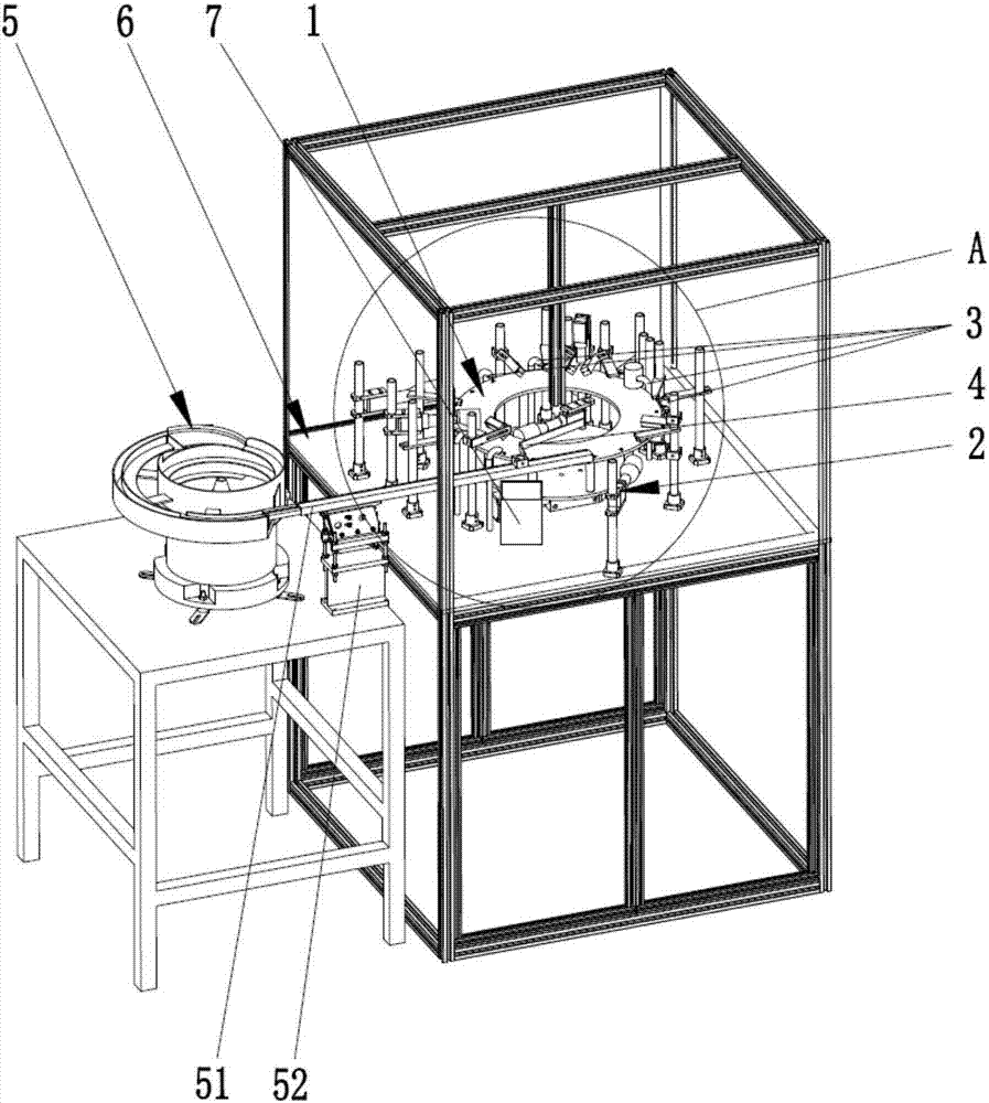
[0043] The invention discloses a parts stereo vision inspection machine, which is suitable for the inspection of small stereo components, as shown in the attached figure 1 As shown, it includes a frame 6, which is provided with a rotatable turntable 1, six shooting stations 2 and a control system,

[0044] The turntable 1 is used to accept the piece to be tested and drive the piece to be tested to rotate;

[0045] The six shooting stations 2 are used to collect images of the six sides of the object to be inspected on the turntable 1;

[0046]The co...


PUM


Abstract

The invention discloses a stereoscopic vision detection machine for parts and a detection method thereof. The detection machine comprises a rotating disc, six shooting stations and a control system, wherein the rotating disc is used for bearing a to-be-detected part and driving the to-be-detected part to rotate; the six shooting stations are used for acquiring six-face images of the to-be-detected part; the control system is at least used for judging whether the to-be-detected part is qualified or unqualified according to the image acquired at each shooting station; when the to-be-detected part is determined to be unqualified, projections of a circular ring formed by a subsequent movement track of the to-be-detected part and a circular ring formed by an initial movement track of the part on the same plane parallel to the rotating disc are concentric and do not coincide with each other. By virtue of the rotating disc made of an optical transparent material, an extra delivery structure does not need to be increased to enable the to-be-detected part to be suspended, and possible damage caused by up-and-down movement of the to-be-detected part is avoided. Moreover, a complicated delivery structure is not needed, the structure is greatly simplified, and partitioned discharging is realized by a dislocation device and a discharging mechanism.

Description

technical field [0001] The invention relates to a visual inspection machine and a detection method thereof, in particular to a component stereo vision detection machine and a detection method thereof. Background technique [0002] Visual inspection is to use machines instead of human eyes for measurement and judgment. Specifically, it refers to converting the captured target into an image signal through machine vision products (ie, image capture devices, such as CMOS and CCD), and sending it to a dedicated image processing system. Pixel distribution, brightness, color and other information are converted into digital signals; the image system performs various operations on these signals to extract the characteristics of the target, and then controls the on-site equipment actions according to the results of the discrimination, which is used for production, assembly or packaging. A valuable mechanism that is invaluable in its ability to detect defects and prevent defective prod...

Claims


Application Information

Patent Timeline
Patent Type & Authority Applications(China)
IPC IPC(8): G01N21/88G05B19/05
CPCG05B19/05G01N21/88G01N21/8806G01N2021/8835
Inventor 张天山邹亚宾吕祥民吴蕾
Owner 张天山
Why Eureka
Try Eureka