Switch cabinet monitoring system

A monitoring system and switchgear technology, applied in the field of switchgear, can solve the problems of inability to observe the operation state of the switchgear intuitively, cannot be effectively monitored, and the monitoring device cannot achieve effective detection, so as to achieve convenient remote monitoring and save manpower, loss reduction effect

Inactive Publication Date: 2017-06-20
合肥羿振电力设备有限公司
View PDF3 Cites 5 Cited by
  • Summary
  • Abstract
  • Description
  • Claims
  • Application Information

AI Technical Summary

Problems solved by technology

[0008] Due to its high voltage level, the monitoring of high-voltage switchgear has always been a problem that is difficult to solve in the industry. Many monitoring devices cannot achieve effective detection results.
[0009] In the prior art, the high-voltage switchgear is mostly monitored by an independent monitoring device. In this way, external staff cannot directly observe the operating status of the switchgear and cannot be effectively monitored.

Method used


Image

  • Switch cabinet monitoring system
  • Switch cabinet monitoring system

Examples


Embodiment 1

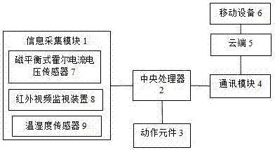
[0025] see figure 1 , this embodiment relates to a switchgear monitoring system, including an information collection module 1, a communication module 4, a central processing unit 2, a cloud 5, a mobile device 6, and an action element 3. The information collection module 1 includes a magnetic balance Hall A current and voltage sensor 7, an infrared video monitoring device 8, a temperature and humidity sensor 9; the information collection module 1, the action element 3, and the communication module 4 are electrically connected to the central processing unit 2 respectively, and the communication module 4 and the cloud 5 signal connection, the cloud 5 and the mobile device 6 signal connection; the magnetic balance type Hall current voltage sensor 7 is used to collect the current and voltage information in the switch cabinet, and the infrared video monitoring device 8 is used to observe the current and voltage information in the switch cabinet. Related action information, the tempe...

Embodiment 2

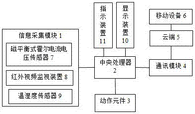
[0035] see figure 2 , this embodiment relates to a switchgear monitoring system, including an information collection module 1, a communication module 4, a central processing unit 2, a cloud 5, a mobile device 6, an action element 3, a display module 10, and an indicator light module 11. The information Acquisition module 1 comprises magnetic balance type Hall current voltage sensor 7, infrared video monitoring device 8, temperature and humidity sensor 9; Described information acquisition module 1, action element 3, communication module 4, display module 10, indicator light module 11 are respectively connected with The central processing unit 2 is electrically connected, the communication module 4 is connected to the cloud 5 for signals, and the cloud 5 is connected to the mobile device 6 for signals; the magnetic balance Hall current voltage sensor 7 is used for collecting switches The current and voltage information in the cabinet, the infrared video monitoring device 8 is u...


PUM


Abstract

The invention discloses a switch cabinet monitoring system, which comprises an information acquisition module, a communication module, a central processing unit, the cloud, a mobile device and an actuating element, and is characterized in that the information acquisition module comprises a magnetic balance type Hall current and voltage sensor, an infrared video monitoring device and a temperature and humidity sensor, the information acquisition module, the actuating element and the communication module are electrically connected with the central processing unit, the communication module is in signal connection with the cloud, and the cloud is in signal connection with the mobile device. Through real-time acquisition for parameters such as images, the temperature and the current in running of a switch cabinet, the switch cabinet monitoring system learns about operating conditions of switch equipment in time, masters the variation trend of the switch equipment and provides a basis for repair and maintenance of the equipment.

Description

technical field [0001] The invention relates to the technical field of switch cabinets, in particular to a switch cabinet monitoring system. Background technique [0002] The switch cabinet is a kind of electrical equipment. The outside line of the switch cabinet first enters the main control switch in the cabinet, and then enters the sub-control switch, and each branch is set according to its needs. Such as instruments, automatic controls, motor magnetic switches, various AC contactors, etc., some also have high-voltage room and low-voltage room switch cabinets, high-voltage busbars, such as power plants, etc. load shedding. [0003] High-voltage switchgear refers to the role of on-off, control or protection in power system power generation, transmission, distribution, power conversion and consumption. High-voltage switchgear is used as electrical products with a voltage level of 3.6kV~550kV, and high-voltage isolating switches And grounding switch, high-voltage load swit...

Claims


Application Information

Patent Timeline
Patent Type & Authority Applications(China)
IPC IPC(8): H02J13/00
CPCH02J13/0006H02J13/0013
Inventor 武行峰
Owner 合肥羿振电力设备有限公司
Why Eureka
Try Eureka