
Refining ladle flow diverter and preparation method thereof

A diverter and ladle technology, which is applied in casting equipment, manufacturing tools, metal processing equipment, etc., can solve the problem of low self-opening rate of ladle, and achieve the effect of large proportion, stable use quality, and market use

Active Publication Date: 2017-06-23
张国令
View PDF9 Cites 4 Cited by
  • Summary
  • Abstract
  • Description
  • Claims
  • Application Information

AI Technical Summary

Problems solved by technology

[0003] The invention provides a refining ladle drainage device and a preparation method thereof, which solves the problem that the ladle self-opening rate is not high in the refining process using the existing ladle drainage device and drainage agent

Method used


Image

  • Refining ladle flow diverter and preparation method thereof
  • Refining ladle flow diverter and preparation method thereof
  • Refining ladle flow diverter and preparation method thereof

Examples


Embodiment 1

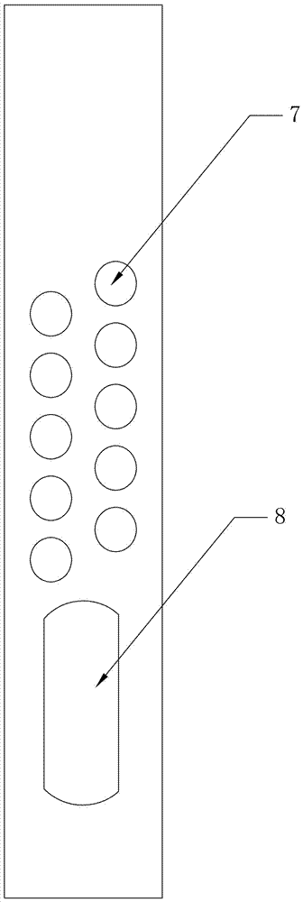
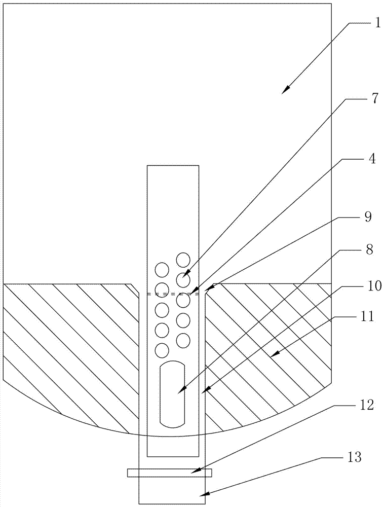
[0030] A refining ladle diverter, comprising a diverter main body 2, the diverter main body 2 is a hollow cylindrical steel pipe with one end sealed, the diverter main body 2 is provided with a diversion hole 7 and a diversion window 8, the The inner wall of the diverter main body 2 is coated with a carbon layer, the diversion hole 7 and the diversion window 8 are sealed by the fusible sheet 3 of the diverter, the open end of the diverter body 2 is sealed by the fusible sheet 6 at the open end, and is located at the drain 13 and the drainer main body 2 of the seat brick 11 are filled with lower filling sand 5, and the drainer main body 2 above the bottom of the bowl of the seat brick 11 is filled with upper filling sand 1, and the upper filling sand 1 and the lower filling sand 5 pass through the middle easily. The melt sheets 4 are separated.

[0031] The outer diameter of the diverter main body 2 is 3-5mm smaller than the inner diameter of the water bag, the height is 1.5-2....

Embodiment 2

[0047] It is basically the same as Example 1, except that the carbon layer includes 96% of flake graphite and 4% of corn dextrin in terms of weight percentage.

[0048] The upper filling sand 1 is calculated by weight percentage, including 75% of foundry chrome sand, 5% of potassium feldspar sand, 8% of washed sea sand, 11% of quartz sand, 0.6% of carbon black, and 0.4% of phosphorus flake graphite.

[0049] The lower filling sand is calculated by weight percentage, 85% of foundry chrome sand, 6% of ceramsite sand, 8% of desert silica sand, and 1% of phosphorus flake graphite.

Embodiment 3

[0051] It is basically the same as Example 1, except that the carbon layer includes 97% of flake graphite and 3% of corn dextrin in terms of weight percentage.

[0052] The upper filling sand 1 is calculated by weight percentage, including 80% of foundry chrome sand, 3% of potassium feldspar sand, 6% of washed sea sand, 10% of quartz sand, 0.7% of carbon black, and 0.3% of phosphorus flake graphite.

[0053] The lower filling sand is calculated by weight percentage, 90% of foundry chrome sand, 4.2% of ceramsite sand, 5% of desert silica sand, and 0.8% of phosphorus flake graphite.


PUM

PropertyMeasurementUnit
The inside diameter ofaaaaaaaaaa
Heightaaaaaaaaaa
Wall thicknessaaaaaaaaaa

Abstract

The invention relates to a refining ladle flow diverter and a preparation method thereof. The flow diverter comprises a flow diverter main body. The flow diverter main body is a hollow cylindrical steel pipe with one end being sealed. Flow guiding holes and a flow guiding window are formed in the flow diverter main body. The refining ladle flow diverter is characterized in that the inner wall of the flow diverter main body is coated with a carbon layer; the flow guiding holes and the flow guiding window are sealed through flow diverter fusible slices; the opening end of the flow diverter main body is sealed through an opening end fusible slice; the positions, located at an water discharging opening and a seating brick part, in the flow diverter main body are filled with lower filling sand; the positions, located above the bottom of a seating brick bowl opening, in the flow diverter main body are filled with upper filling sand; and the upper filling sand and the lower filling sand are separated through an intermediate fusible slice. According to the flow diverter, operation of a using customer is simplified, the pouring rate is increased to 98% or above, and the using quality of a product is stable. Compared with traditional flow diversion sand, the problem of the quality fluctuation of the product is avoided, and market use is met.

Description

technical field [0001] The invention relates to a refining ladle drainage device and a preparation method thereof, belonging to a ladle drainage device. Background technique [0002] After nearly ten years of rapid development of my country's steel industry, the output of crude steel has increased from 130 million tons in 2000 to 803.83 million tons in 2015, and the quality of products has also achieved rapid development. However, today's steel industry is facing a bottleneck period of development. On the one hand, it is the disorderly expansion of production capacity, and on the other hand, it is the sharp decline in the industry's profit margin. With the obvious overcapacity of domestic iron and steel, the operation of iron and steel enterprises is in trouble, and the era of high profit growth in the iron and steel industry is difficult to reproduce, and it is entering a long period of adjustment. All iron and steel enterprises have lowered the purchase price of various r...

Claims


Application Information

Patent Timeline
IPC IPC(8): B22D41/48
CPCB22D41/48
Inventor 张国令
Owner 张国令
Learn More