
A Method for Suppressing Additional Zero Offset of Interferometric Fiber Optic Gyroscope Output Signal Based on Median Filtering

A technology of fiber optic gyroscope and output signal, which is applied in the direction of Sagnac effect gyroscope, gyroscope/steering sensing equipment, instrument, etc. High reliability, high precision and other issues to achieve the effect of reducing additional zero offset and suppressing additional zero offset

Active Publication Date: 2020-02-07
BEIHANG UNIV
View PDF15 Cites 0 Cited by
  • Summary
  • Abstract
  • Description
  • Claims
  • Application Information

AI Technical Summary

Problems solved by technology

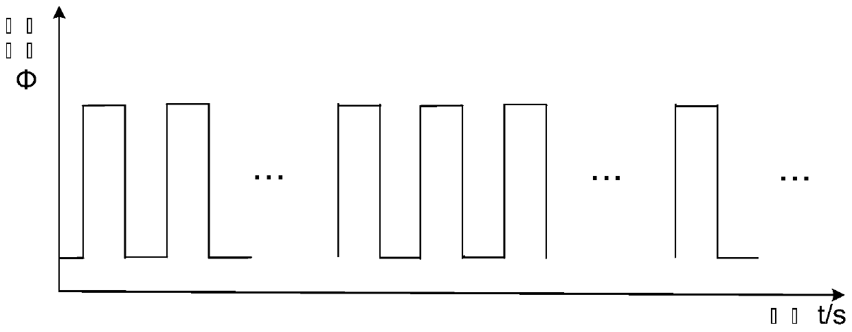
[0005] The periodic pulse interference contained in the detection signal is mainly divided into odd frequency multiplication interference and even frequency multiplication interference of the detection signal. The commonly used coherent demodulation method can effectively suppress random pulse interference and even frequency multiplication interference in the signal , but the processing method for the odd frequency multiplier interference in the signal is limited, resulting in an additional zero bias in the output signal of the fiber optic gyroscope, which in turn causes the accuracy of the fiber optic gyroscope to deteriorate with time, and cannot meet the high reliability and high precision requirements of the gyroscope

Method used


Image

  • A Method for Suppressing Additional Zero Offset of Interferometric Fiber Optic Gyroscope Output Signal Based on Median Filtering
  • A Method for Suppressing Additional Zero Offset of Interferometric Fiber Optic Gyroscope Output Signal Based on Median Filtering
  • A Method for Suppressing Additional Zero Offset of Interferometric Fiber Optic Gyroscope Output Signal Based on Median Filtering

Examples


Embodiment Construction

[0029] The present invention will be further described in detail with reference to the accompanying drawings and embodiments.

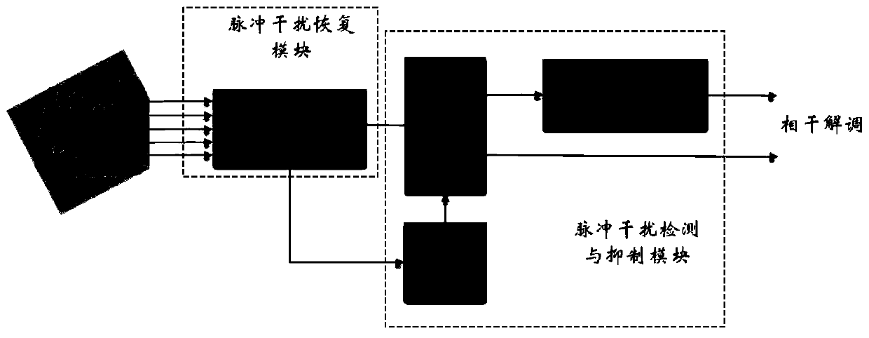
[0030] A method for suppressing the additional zero bias of the interferometric fiber optic gyroscope output signal based on median filtering in the present invention, such as figure 1 As shown, it mainly includes two parts: the pulse interference recovery module and the pulse interference detection and suppression module.

[0031] The pulse interference recovery module adopts a multi-point signal averaging algorithm, and the detection signal generated by accumulating signals in units of periods will lead to an extension of the feedback cycle and affect the gyroscope closed-loop feedback speed. Therefore, the multi-point signal averaging algorithm of the present invention The moving average method is used to restore the detection signal containing periodic pulse interference and improve the signal-to-noise ratio of the detection signal.

[0032] The ...


PUM


Abstract

The invention provides an inhibition method for additional zero offset of an output signal of an interference fiber-optic gyroscope based on median filtering and relates to the technical field of interference fiber-optic gyroscopes. A pulse interference recovery module and a pulse interference detection and inhibition module are mainly utilized. The pulse interference recovery module is used for carrying out N times of accumulation on a detection signal through a multi-point signal average algorithm adopting a moving average manner; periodic pulse interference is removed through a median filter and then coherent demodulation is carried out; finally, K / N times of accumulation is carried out on the detection signal subjected to the coherent demodulation. The pulse interference detection and inhibition module adopts a convolution form; a detection module is used for judging a sampling point subjected to pulse interference; an inhibition module is used for filtering interference in the detection signal by adopting a rapid median filtering algorithm. Based on an original structure of the interference fiber-optic gyroscope, periodic pulse signal interference is eliminated from the detection signal and the additional zero offset in the output signal is reduced; additional delaying of signal processing is not generated; meanwhile, an inhibition capability on random noises is guaranteed.

Description

technical field [0001] The invention relates to the technical field of interferometric fiber optic gyroscopes, in particular to a method for suppressing additional zero bias of output signals of interferometric fiber optic gyroscopes based on median filtering. Background technique [0002] The interferometric fiber optic gyroscope is a highly reliable and high-precision inertial angular velocity sensor. It is sensitive to the angular velocity to be measured through the optical fiber ring and produces a non-reciprocal phase difference. It has the advantages of large dynamic range, no moving parts, and shock resistance. It can be widely used in Measuring the attitude angle and angular velocity of the vehicle is the core device that constitutes the inertial system. [0003] The structure of the interferometric fiber optic gyroscope mainly includes a light source, a coupler, a Y waveguide, a fiber optic ring, a detector and a signal processing device. In the interferometric fib...

Claims


Application Information

Patent Timeline
Patent Type & Authority Patents(China)
IPC IPC(8): G01C19/72G01D3/036
CPCG01C19/721G01D3/036
Inventor 金靖马坤滕飞潘雄徐小斌宋镜明
Owner BEIHANG UNIV
Learn More