

Automatic laser scanning galvanometer correction equipment and laser galvanometer equipment
A technology of laser scanning galvanometer and correction equipment, applied in laser welding equipment, welding equipment, metal processing equipment and other directions, can solve the problems of low degree of automation, small correction width, low precision of correction method, etc., to achieve easy installation and use, The effect of accurate calibration and reduction of manual measurement errors
- Summary
- Abstract
- Description
- Claims
- Application Information
AI Technical Summary
Problems solved by technology
Method used
Image

Examples
Embodiment Construction
[0012] In order to make the object, technical solution and advantages of the present invention clearer, the present invention will be further described in detail below in conjunction with the accompanying drawings and embodiments. It should be understood that the specific embodiments described here are only used to explain the present invention, not to limit the present invention.
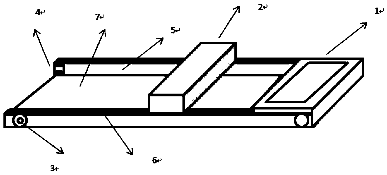
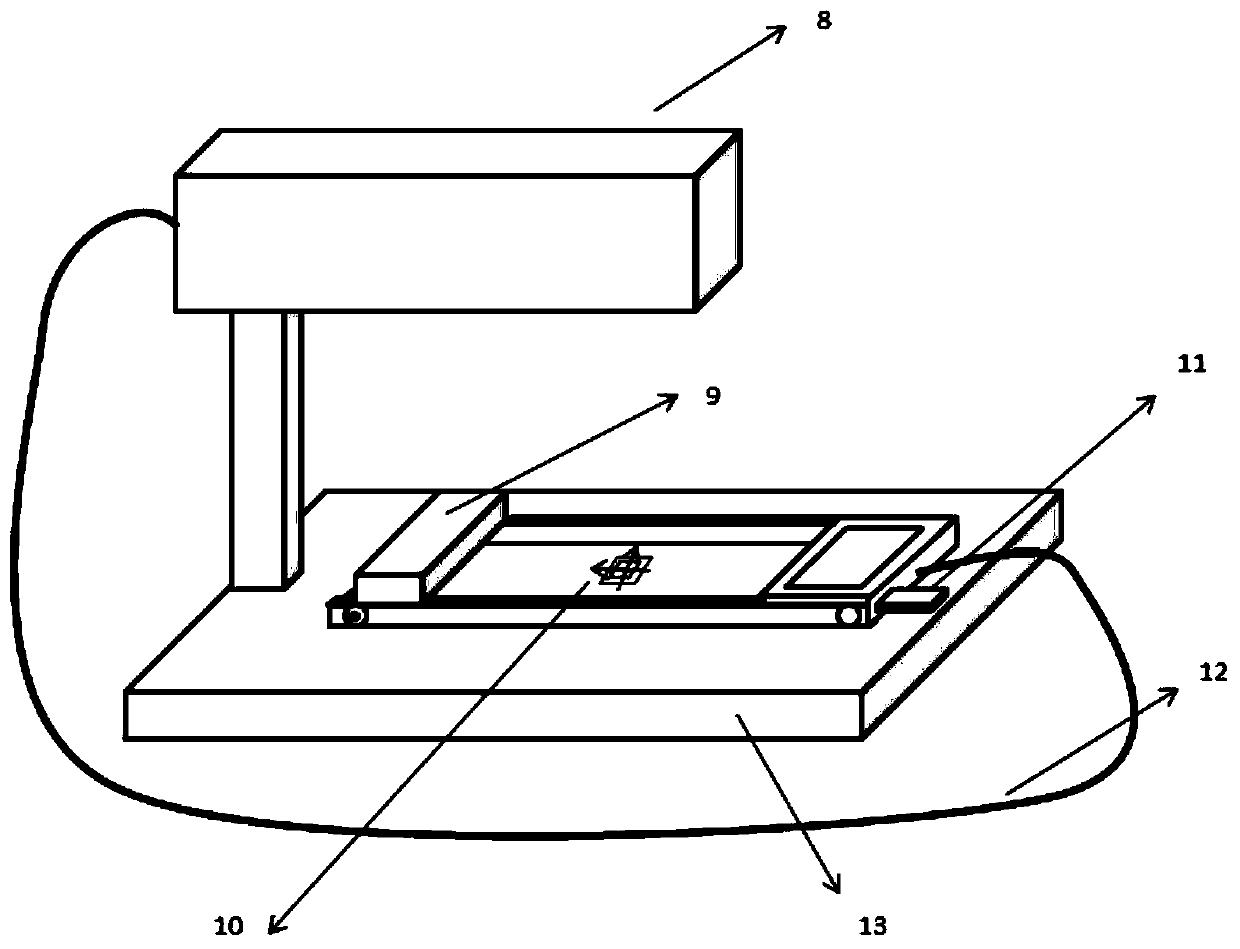
[0013] The invention provides a universal automatic laser galvanometer calibration device, which can automatically calibrate the laser scanning galvanometer, has no manual measurement error, has high measurement accuracy, can correct large-format galvanometers, and is convenient to place, and is suitable for the market. Most of the laser galvanometer equipment.
[0014] A universal automatic laser vibrating mirror correction device provided by the present invention includes: a control box, a guide rail, a scanning head, a stepping motor control module, a conveyor belt, photosensitive paper, and a p...
PUM
 Abstract
Description
Claims
Application Information