Aluminum film welding machine

A welding machine and aluminum film technology, applied in the field of medical equipment, can solve the problems of inaccurate punching and welding of powder liquid bags, waste bags, waste of powder liquid bags, etc.

Pending Publication Date: 2017-06-27
SHINVA MEDICAL INSTR CO LTD
View PDF0 Cites 4 Cited by
  • Summary
  • Abstract
  • Description
  • Claims
  • Application Information

AI Technical Summary

Problems solved by technology

[0003] The existing aluminum film welding machine adopts the positioning method of the mouth tube of the powder liquid bag and the bag hanging hole at the tail. The bag is positioned horizontally, and the drive system drives the powder liquid bag forward. The aluminum film needs to follow the powder liquid bag and follow the powder liquid bag during the process. Complete virtual welding, peripheral welding, and tail welding, and then die-cut and modify it to become an existing product. Since the powder-liquid bag is perpendicular to its forward direction, the tail needs to be disengaged from the bag-hanging hole before peripheral welding. Only the powder-liquid bag with the mouth tube positioning is easy. Deviation occurs, resulting in deviation of welding position and waste bags
The aluminum film is not punched when the film is applied, causing the aluminum film to follow the powder liquid bag all the time. If the pulling film and the powder liquid bag are not synchronized, the punching and welding of the powder liquid bag will be inaccurate. Pull the film to the punching position before running, the powder liquid bag in front will cause waste

Method used


Image

  • Aluminum film welding machine
  • Aluminum film welding machine
  • Aluminum film welding machine

Examples


Embodiment Construction

[0035] The technical solutions in the embodiments of the present invention will be clearly and completely described below in conjunction with the accompanying drawings in the embodiments of the present invention. Obviously, the described embodiments are only a part of the embodiments of the present invention, rather than all the embodiments. Based on the embodiments of the present invention, all other embodiments obtained by those of ordinary skill in the art without creative work shall fall within the protection scope of the present invention.

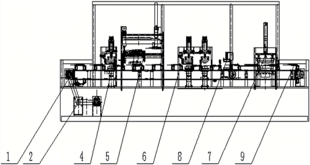
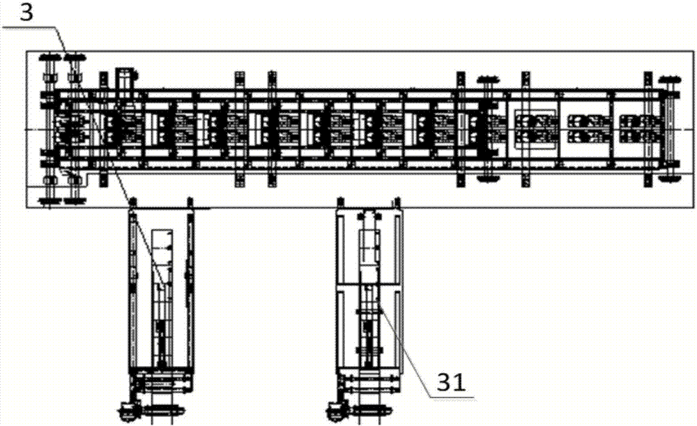
[0036] Please refer to figure 1 with figure 2 , figure 1 Is a schematic diagram of the overall structure of a specific implementation provided by the present invention; figure 2 for figure 1 A top view of the overall structure shown.

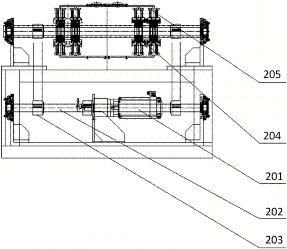
[0037] In a specific embodiment provided by the present invention, the aluminum film welding machine mainly includes an automatic bag loading device 1, a drive system 2, an aluminum film punching and film l...


PUM


Abstract

The invention discloses an aluminum film welding machine which comprises a driving system, an automatic bag feeding device, a first aluminum film punching and feeding device, a second aluminum film punching and feeding device, a bag turnover device, a cooling device, a punching device and a bag discharging device, wherein the driving system is used for conveying powder liquid bags; the automatic bag feeding device is used for transferring the powder liquid bags to a clamping device on the driving system; the first aluminum film punching and feeding device is used for punching a continuous aluminum film into cut films of defined sizes and transferring the cut films to a first welding device; the second aluminum film punching and feeding device is used for punching the continuous aluminum film into cut films of defined sizes and transferring the cut films to a second welding device; the bag turnover device is arranged between the first welding device and the second welding device and used for turning over the powder liquid bags subjected to single-side welding by the first welding device by 180 degrees; the cooling device is used for cooling the powder liquid bags subjected to double side welding; the punching device is used for punching the cooled powder liquid bags; the bag discharging device is used for discharging the punched powder liquid bags. According to the aluminum film welding machine, as the cut films are utilized to be welded on the liquid powder bags, the multiple purposes that the aluminum film welding position accuracy is improved and meanwhile the waste of the aluminum film during the cut film welding process is reduced are achieved.

Description

Technical field [0001] The present invention relates to the technical field of medical devices, in particular to an aluminum film welding machine. Background technique [0002] At present, the domestic soft bag large infusion film material is non-PVC multi-layer co-extruded film, which has high drug compatibility, transparency, extremely low water vapor transmission rate, impact resistance, and light weight. The cavity needs to be filled with powder medicines. The medicines need to be insulated from air and ultraviolet rays. The powder cavity needs to be packaged with functions such as light blocking, oxygen blocking, and gas blocking, so as to effectively protect the medicines in the powder cavity. The soft bag is covered with a layer of aluminum film. [0003] The existing aluminum film welding machine adopts the positioning method of the powder liquid bag mouth tube and the tail hanging bag hole, the bag is positioned horizontally, and the drive system drives the powder liquid ...

Claims


Application Information

Patent Timeline
IPC IPC(8): B29C65/74B29C65/78
CPCB29C65/7419B29C65/745B29C65/7457B29C65/7841B29C65/7861B29C66/0342B29C66/8511Y02E60/10
Inventor 高斯潘旭辉张强王振明
Owner SHINVA MEDICAL INSTR CO LTD
Why Eureka
Try Eureka