Joint simulation method for vehicle-road coupled vibration system

A technology of coupled vibration and co-simulation, applied in the field of vehicle engineering, can solve the problems of difficult to ensure the calculation accuracy, the contact unit cannot accurately simulate the vehicle-road coupling relationship, etc., to achieve the effect of high accuracy and simple operation

Inactive Publication Date: 2017-06-27
WUHAN UNIV OF SCI & TECH
View PDF2 Cites 17 Cited by
  • Summary
  • Abstract
  • Description
  • Claims
  • Application Information

AI Technical Summary

Problems solved by technology

So far, there are two research methods on the dynamics of the vehicle-road coupling system: one is to simulate the dynamics of the vehicle-road coupling system by establishing the partial differential equation of the vehicle-road coupling vibration system, and often using the direct numerical integration method Response, the researchers need to write the solution program of the dynamic equation by themselves, which is not easy to guarantee the calculation accuracy; the other is to establish the discrete mass vehicle model and the finite element road surface model in Ansys, and realize the vehicle-road coupling relationship through contact elements, which can Linear or nonlinear transient solution, although this method utilizes the computing power of engineering software, it is not suitable for complex vehicle dynamic models, and the contact element cannot accurately simulate the vehicle-road coupling relationship

Method used


Image

  • Joint simulation method for vehicle-road coupled vibration system
  • Joint simulation method for vehicle-road coupled vibration system
  • Joint simulation method for vehicle-road coupled vibration system

Examples


Embodiment 1

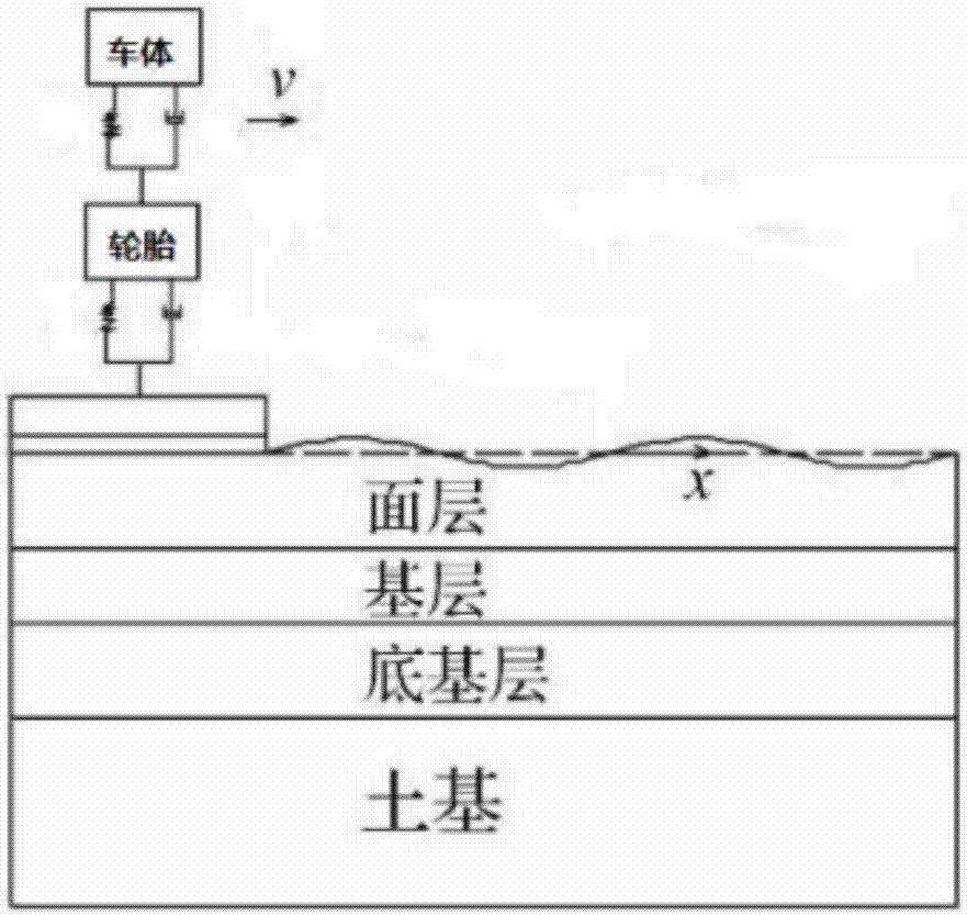
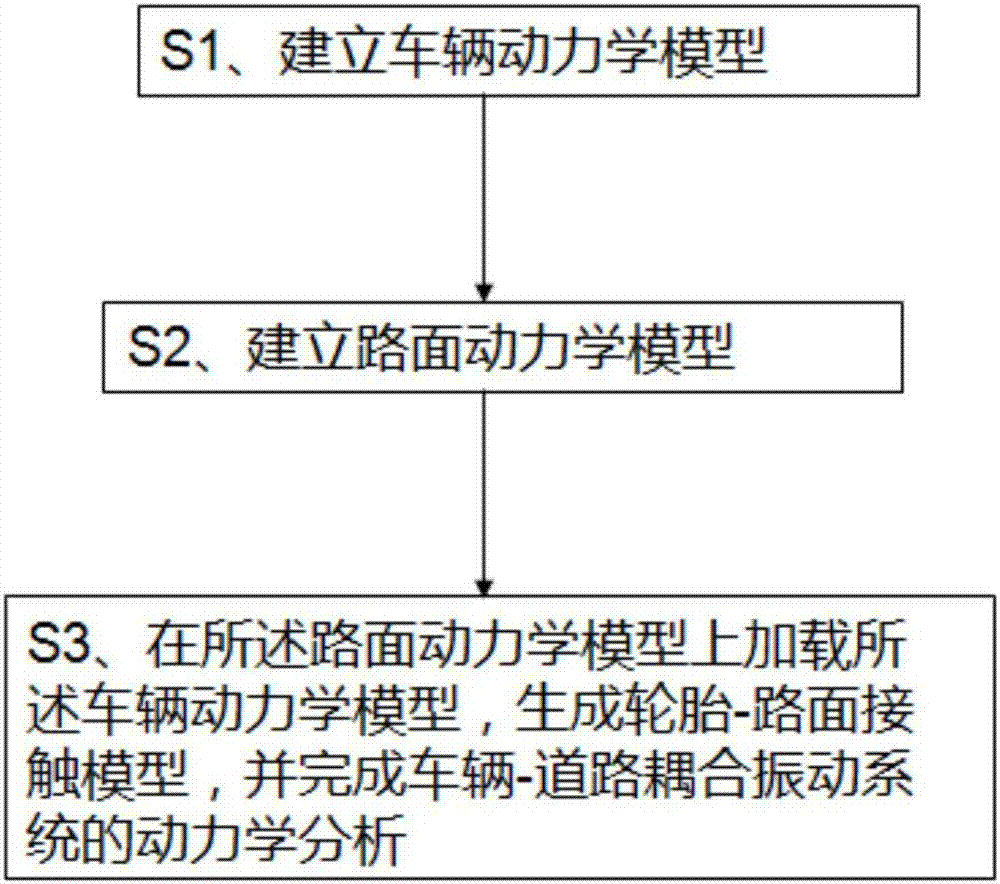
[0060] figure 1 shows a schematic diagram of a vehicle-road coupling system in the prior art, figure 2 Then, the vehicle-road coupled vibration system co-simulation method of the present invention is shown, which includes the following steps:

[0061] S1, establish vehicle dynamics model according to dynamics equation (1)-(2); Described dynamics equation (1)-(2) is as follows respectively:

[0062]

[0063]

[0064] Among them, m s is the sprung mass; k s is the suspension stiffness, c s is the suspension damping, x s is the body displacement, m u is the unsprung mass, k t is the tire stiffness, c t is the tire damping, x u is the tire displacement, x r Enter the sum of the road surface roughness and the vertical displacement of the road surface;

[0065] Preferably, in the step S1, according to modern control theory, the state vectors of the dynamic equations (1)-(2) are: The output vector is:

[0066] in, is the body acceleration, is the tire accele...


PUM


Abstract

The invention relates to a joint simulation method for a vehicle-road coupled vibration system. The method comprises the following steps of S1, building a vehicle dynamics model according to a dynamics equation; S2, building a pavement dynamics model according to a structural mechanics finite element equation; and S3, loading the vehicle dynamics model in the pavement dynamics model to generate a tire-pavement contact model, and finishing dynamics analysis of the vehicle-road coupled vibration system. According to the method, joint modeling of the vehicle-road coupled vibration system is realized by adopting efficient engineering software Matlab and Ansys; and by taking Matlab as control software and performing secondary development on Ansys, joint simulation of Matlab and Ansys is realized, and dynamics analysis of the vehicle-road coupled vibration system under complex road and vehicle conditions is finished.

Description

technical field [0001] The invention relates to the field of vehicle engineering, in particular to a vehicle-road coupled vibration system joint simulation method. Background technique [0002] Traditional vehicle dynamics and road dynamics do not study the coupling relationship between the vehicle and the road. In vehicle dynamics, road surface roughness is usually used as an input to study the vibration problem of the vehicle, that is, the ride comfort of the vehicle, while road surface dynamics is to load the static load or dynamic load of the vehicle on the road surface model to study the dynamic response of the road surface , to check the structural strength of the pavement. In fact, when a vehicle is driving on the road at a certain speed, the vehicle and the road surface are an interactive process. The unevenness of the road surface causes the vehicle to generate random vibrations; Deformation, the vibration of the road surface in turn affects the driving vehicle, t...

Claims


Application Information

Patent Timeline
Patent Type & Authority Applications(China)
IPC IPC(8): G06F17/50
CPCG06F30/15G06F30/20Y02T90/00
Inventor 杨啟梁李星宇
Owner WUHAN UNIV OF SCI & TECH
Why Eureka
Try Eureka