
Tube cleaner speed control unit

A technology for a pig and an installation ring, which is applied in the directions of cleaning hollow objects, cleaning methods and utensils, chemical instruments and methods, etc. It can solve the problems such as the increase of flow loss around the device, and achieve the effect of stable operation, improving the passability of the curve and reducing the local vibration.

Active Publication Date: 2017-06-30
XIHUA UNIV
View PDF9 Cites 15 Cited by
  • Summary
  • Abstract
  • Description
  • Claims
  • Application Information

AI Technical Summary

Problems solved by technology

The discharge valve of the pipe pig generally adopts a rotary valve structure, which is composed of a rotary valve moving vane and a rotary valve static vane. This structure has the following problems: 1. When the rotary valve body is impacted and deformed, interference between the vanes is easy to occur. The speed control rotary valve is stuck, and the operating speed of the pig cannot be adjusted; 2. In order to meet the demand for operating torque of the rotary valve, the pig needs to be equipped with a high-power motor and a large-capacity battery, which will occupy the interior of the pig 3. The rotary valve is generally installed at the end of the pig, which increases the length of the pig and reduces the bend passability of the pig; 4 , There is a sudden change in the flow state of the fluid at the back end of the rotor vane, which increases the local flow loss of the pig, and at the same time, the local flow will also cause the overall vibration of the pig, which not only increases the pressure in the pipeline transportation process Energy loss also affects the normal operation of the equipment

Method used


Image

  • Tube cleaner speed control unit
  • Tube cleaner speed control unit
  • Tube cleaner speed control unit

Examples


Embodiment Construction

[0045] The structure of the pig speed control device of the present invention will be further described through the embodiments and in conjunction with the accompanying drawings. In the following embodiments, programmable logic controllers, encoders, and stepper motors are purchased from the market.

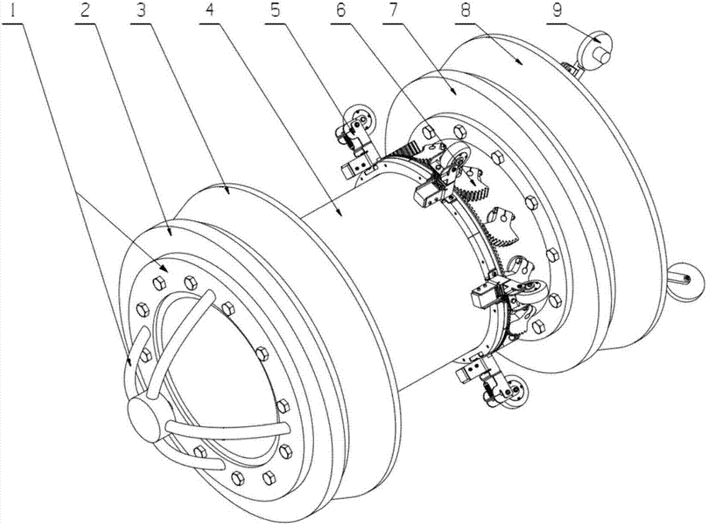
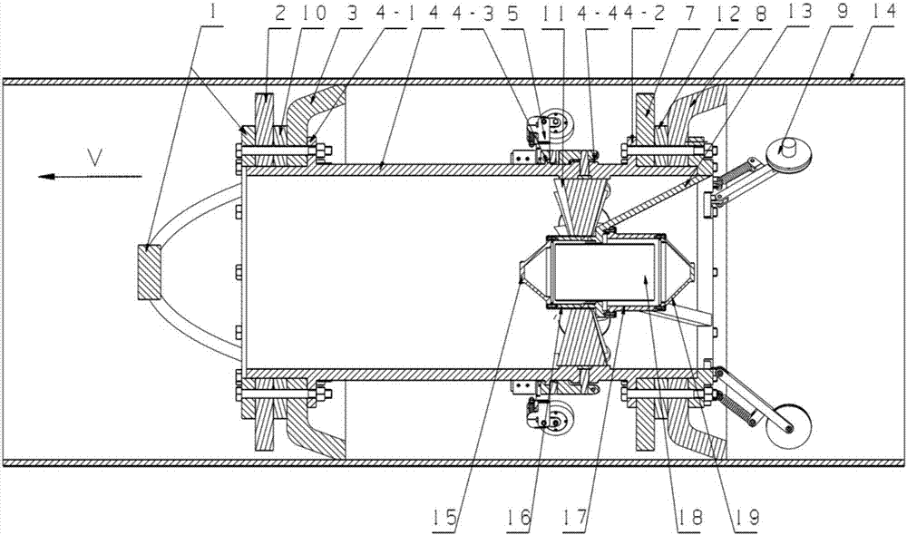
[0046] In this embodiment, the pig speed control device such as figure 1 , figure 2 As shown, it includes outer skeleton 4, inner skeleton 13, anti-collision support 1, front cup assembly, rear cup assembly, mileage wheel assembly 9, speed control rotary valve, control system 18 and a sealed chamber for placing the control system.

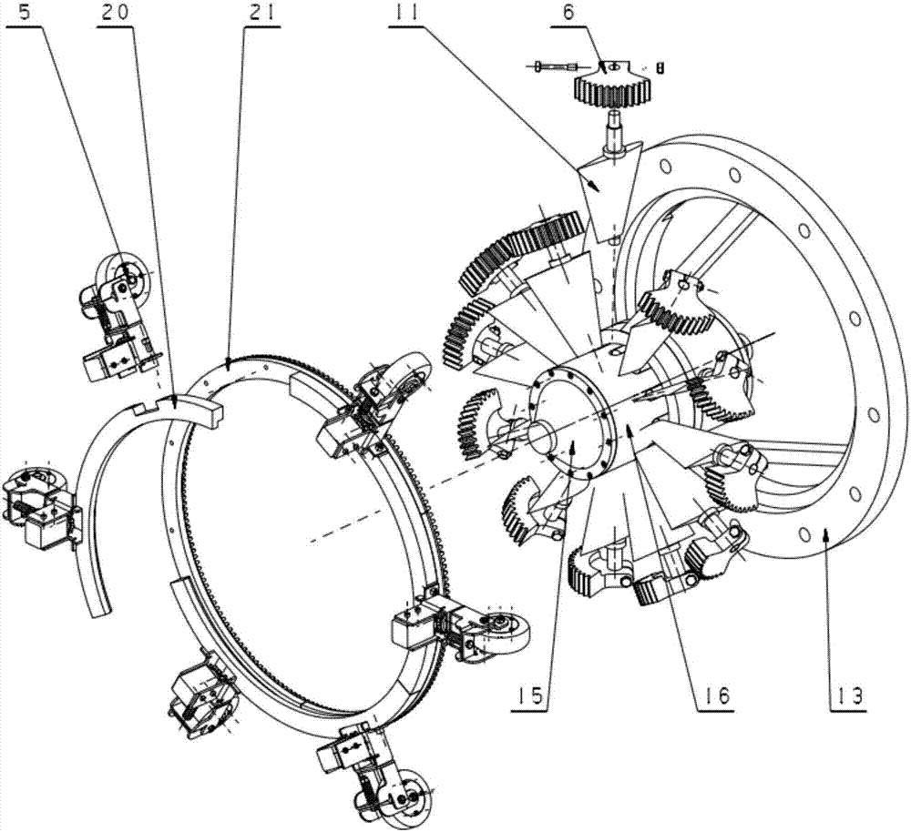
[0047] The speed control rotary valve is as image 3 As shown, it is composed of movable airfoil fan blade 11 and a circumferential control mechanism; movable airfoil fan blade 11 is as Figure 7 , Figure 8 , Figure 9 As shown, by the airfoil blade 11-4 and the first journal 11-5 positioned at one end of the airfoil blade 11-4, the collar 11-3...


PUM


Abstract

A tube cleaner speed control unit comprises an outer framework, an inner framework, a collision-proof support, a front leather cup assembly, a rear leather cup assembly, an odometer wheel assembly, a speed control rotary valve, a control system and a sealing silo used for storing the control system; the speed control rotary valve is composed of movable wing-type blades and a circumferential control mechanism which is composed of a reverse wheel assembly, an installation ring, a gear ring and a fan-shaped gear; the received real-time running speed, detected through the odometer wheel assembly, of a tube cleaner is compared with the set running speed of the tube cleaner by the control system, and according to the difference of the real-time running speed of the tube cleaner and the set running speed of the tube cleaner, rotating direction of a motor shaft in the reverse wheel assembly is controlled, so that a transmission pair is formed by the gear faces of the fan-shaped gear and the gear ring which are located in the speed control rotary valve to drive the movable wing-type blades to rotate; and the discharging quantity of an annular flow channel is changed, so that the tube cleaner works according to the set running speed.

Description

technical field [0001] The invention belongs to the field of oil and gas pipeline pigging, and relates to a speed control device for a pig. Background technique [0002] If the pipelines transporting dangerous fluids such as oil and natural gas run for a long time, there are bound to be potential safety hazards. In order to ensure the normal operation of the pipeline, it is necessary to regularly carry out pigging and testing operations on the pipeline. The purpose of pigging is to clean the sundries, liquid accumulation and dirt accumulation in the pipeline, improve pipeline transportation efficiency and reduce friction loss. These pipeline defects are precisely located to provide reliable information for later pipeline maintenance. [0003] At present, the mainstream pigs mainly rely on the pressure difference formed by the blocking effect on the transport medium in the pipeline to drive forward. However, due to the fluctuation of the upstream and downstream pressure of ...

Claims


Application Information

Patent Timeline
Patent Type & Authority Applications(China)
IPC IPC(8): B08B9/055
CPCB08B9/055B08B9/0551
Inventor 张均富赵上马杨梦鸥程创
Owner XIHUA UNIV
Learn More