
Method for controlling a setting process for re-setting a yarn at a work station of a textile machine

A technology for textile machines and yarns, which is applied in the field of control wiring technology and can solve problems such as affecting machine efficiency.

Active Publication Date: 2017-06-30
RIETER INGOLSTADT GMBH
View PDF9 Cites 0 Cited by
  • Summary
  • Abstract
  • Description
  • Claims
  • Application Information

AI Technical Summary

Problems solved by technology

Of course, this efficiency rating-oriented control of individual work steps often affects machine efficiency

Method used

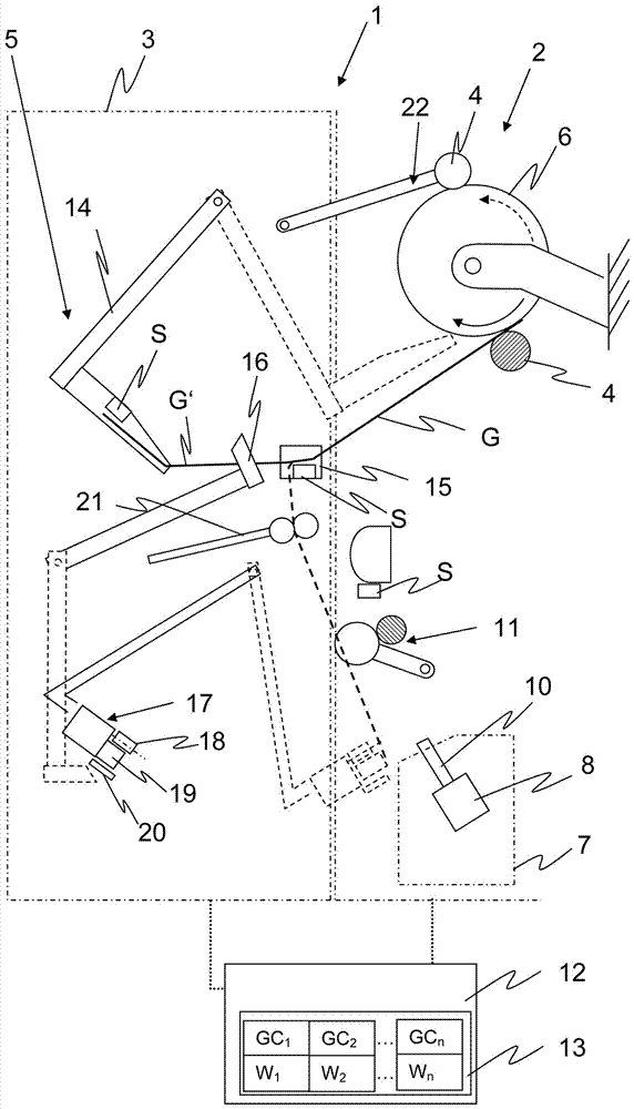
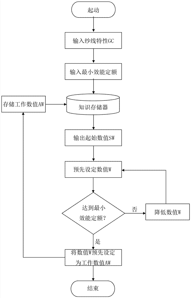

Image

  • Method for controlling a setting process for re-setting a yarn at a work station of a textile machine
  • Method for controlling a setting process for re-setting a yarn at a work station of a textile machine

Examples


Embodiment Construction

[0038] figure 1 The weaving station 2 of the weaving machine 1 is shown in a schematic side view. The textile machine 1 usually has a plurality of weaving stations 2 arranged next to each other, which each have a plurality of working elements, which are used to produce the yarn G. For this purpose, each weaving station 2 has at least a weaving unit 7 with a weaving element 8 and a withdrawal mechanism 10 . The yarn F produced by the textile element 8 is withdrawn by the withdrawal device 11 during a conventional spinning operation and supplied to the bobbin 6 on which the yarn is wound. For this purpose, the bobbin 6 is mounted rotatably and drivably, wherein a roller 4 is provided here for driving the bobbin 6 . In a conventional spinning operation, the bobbin 6 is driven by the rollers 4 in the yarn withdrawal direction (dashed arrow). As an alternative to this, the bobbin 6 can also be driven by a direct drive.

[0039] Furthermore, the textile machine 1 has along the t...


PUM


Abstract

With a method for controlling a setting process for re-setting a yarn (G) at a textile machine, in particular a spinning machine (1), by means of a setting device (5), a multiple number of work steps as preparation for the actual setting operation are carried out successively in a chronological sequence. In each case, a predetermined time period is allocated to the work steps within which the respective work step is carried out. For at least one of the work steps, the predetermined time period can be varied, whereas the current time period of the at least one work step is determined as a function of a yarn characteristic (GC) of the currently produced yarn (G and / or as a function of a utilization of the setting device (5). A textile machine features a control unit (12), which is designed to operate the textile machine according to this method.

Description

technical field [0001] The invention relates to a method for controlling the joining process in order to join yarns, in particular to join yarns again, at workstations of textile machines by means of a joining device. In the wiring process, a plurality of work steps (which prepare the way for the joining process) are carried out in chronological order, wherein these work steps each have a predetermined duration within which the respective work step is carried out. Background technique [0002] In modern open weaving machines, the ply threads are mainly joined automatically after the ply threads have been broken or cut by the yarn clearer, either by a robot movable along the weaving station of the open weaving machine or by the weaving station itself The operating mechanism to perform the wiring work. In each case, for joining the yarn, a plurality of preparatory work steps are firstly required, which are carried out sequentially in chronological order or partially parallel ...

Claims


Application Information

Patent Timeline
Patent Type & Authority Applications(China)
IPC IPC(8): D01H4/48D01H15/00
CPCD01H4/48D01H15/00B65H54/26B65H67/081B65H69/061B65H2701/31D01H4/24D01H15/002D01H4/50
Inventor A·斯蒂芬
Owner RIETER INGOLSTADT GMBH
Learn More