Drying system for drying granular materials

A technology of granular material and drying system, applied in the direction of granular material drying, drying, dryer, etc., can solve the problem of large total energy consumption for secondary drying of the dryer, and save the total energy consumption and efficiency. high effect

Active Publication Date: 2019-06-25
攸县晟煌环保科技有限公司
View PDF7 Cites 0 Cited by
  • Summary
  • Abstract
  • Description
  • Claims
  • Application Information

AI Technical Summary

Problems solved by technology

[0004] The technical problem to be solved by the present invention is that the total energy consumption of the secondary drying of the dryer is large, and the purpose is to provide a drying system for drying granular materials, so as to solve the problem of large total energy consumption of the secondary drying of the dryer

Method used


Image

  • Drying system for drying granular materials

Examples


Embodiment 1

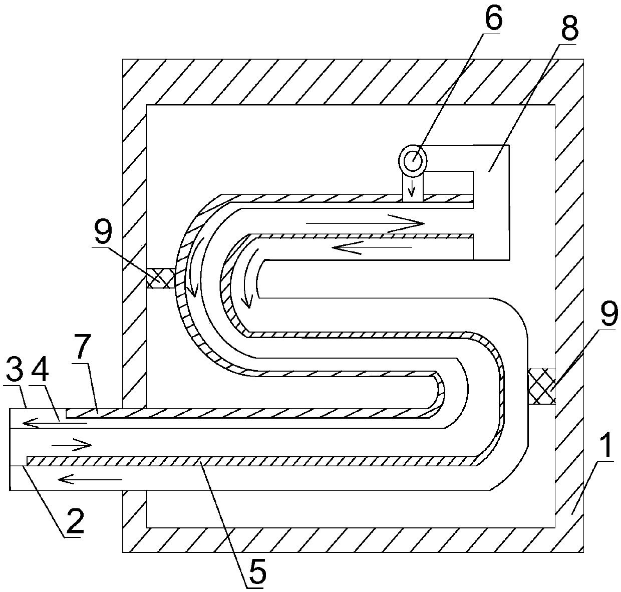
[0022] Such as figure 1 As shown, the drying system for drying granular materials of the present invention includes a body 1, a drying pipe is installed inside the body 1, and the drying pipe includes a serpentine heating pipe 2, which is sleeved on the outside of the serpentine heating pipe 2. Serpentine sleeve 3, there is an annular channel 4 between the serpentine sleeve 3 and the serpentine heating tube 2, the inner wall of the serpentine heating tube 2 is covered with an electric heating film 5, the inlet of the serpentine heating tube 2 The feed port is located at the bottom of the body 1, and the discharge port of the serpentine heating tube 2 is located at the top of the body 1. The discharge port of the serpentine heating tube 2 is connected with a circulation pump 6, and the discharge port of the circulation pump 6 is connected to the inlet of the annular channel 4. The feed port is connected, the feed port of the annular channel 4 is close to the discharge port of t...

Embodiment 2

[0025] Based on Example 1, the inner wall of the serpentine sleeve 3 is covered with a thermal insulation layer 7, the thermal insulation layer 7 includes a silicone rubber layer bonded to the inner wall of the serpentine sleeve 3, and the silicone rubber layer is close to the snake. The surface of the shaped heating pipe 2 is covered with a polyurethane insulation layer. The insulation layer is used to prevent heat loss inside the annular channel and keep the heat in the annular channel sufficient to dry materials. Silicone rubber not only has the good adhesiveness of rubber, but also has the moisture-proof, waterproof, temperature-resistant and insulating properties of silicone, and the thermal insulation performance of polyurethane. Well, it can effectively prevent heat loss.

Embodiment 3

[0027] Based on the above embodiment, a plurality of springs 9 are connected between the outer wall of the serpentine sleeve 3 and the inner wall of the body 1 , and each spring 9 is sleeved with a casing. The spring has a shock absorbing effect, and the materials entering the serpentine heating tube and the annular channel are all pressurized, and the spring has a certain buffering effect to avoid unstable fixation between the serpentine sleeve and the body; the outer shell of the spring is used for Therefore, when the spring is deformed, the displacement and deflection will not occur, so that the service life of the spring is longer, and the connection between the serpentine sleeve and the inner wall of the body is stronger.


PUM


Abstract

The invention discloses a drying system for drying particulate materials. The drying system comprises a machine body. A drying pipe is installed in the machine body and comprises a snakelike heating pipe and a snakelike casing connected outside the snakelike heating pipe in a sleeving mode. An annular channel is reserved between the snakelike casing and the snakelike heating pipe. The inner wall of the heating pipe is covered with an electric heating thin film. A feed inlet of the snakelike heating pipe is located in the bottom of the machine body. A discharge outlet of the snakelike heating pipe is located in the top of the machine body and communicates with a circulating pump. A discharge outlet of the circulating pump communicates with a feed inlet of the annular channel. The feed inlet of the annular channel is close to the discharge outlet of the snakelike heating pipe. A discharge outlet of the annular channel is located at the feed inlet of the snakelike heating pipe. The pipe wall of the snakelike heating pipe is a heat conduction pipe wall. The annular channel between the snakelike casing and the snakelike heating pipe reheats the materials through heat generated by the snakelike heating pipe, and thus the total energy consumption of reheating of the materials is reduced.

Description

technical field [0001] The invention relates to a drying device, in particular to a drying system for drying granular materials. Background technique [0002] The dryer has several modes such as belt drying, drum drying, box drying, tower drying, etc.; the heat source includes coal, electricity, gas, etc.; the drying process of materials has hot air flow type and radiation type, etc. , The hot air drum drying is that the hot air flow moves forward from the tail, fully contacts with the material, and makes full use of the heat transfer through heat conduction, convection, and radiation; the heat energy is directly transferred to the material, so that the moisture of the material is continuously evaporated in the cylinder. [0003] In the traditional dryer, the material is dried from the inlet and outlet of the dryer. If the degree of the first drying does not meet the requirements, the material needs to be dried a second time, even if the second time The drying temperature o...

Claims


Application Information

Patent Timeline
Patent Type & Authority Patents(China)
IPC IPC(8): F26B17/00F26B23/06F26B25/00
CPCF26B17/00F26B23/06F26B25/00F26B2200/08
Inventor 陈杰邓建国王刚新
Owner 攸县晟煌环保科技有限公司
Why Eureka
Try Eureka