Laminated composite reflecting film and manufacturing method thereof

A reflective film and layered structure technology, applied in optics, instruments, nonlinear optics, etc., can solve the problems of poor luminance performance and poor stiffness of optical reflective films, achieve good luminance performance, reduce production costs, and improve reflection effect of ability

Active Publication Date: 2017-06-30
NINGBO CHANGYANG TECH
View PDF9 Cites 6 Cited by
  • Summary
  • Abstract
  • Description
  • Claims
  • Application Information

AI Technical Summary

Problems solved by technology

[0007] In order to solve the problems of poor luminance and poor stiffness of existing optical reflective films, the present invention provides a layered laminated reflective film and its manufacturing method

Method used


Image

  • Laminated composite reflecting film and manufacturing method thereof
  • Laminated composite reflecting film and manufacturing method thereof
  • Laminated composite reflecting film and manufacturing method thereof

Examples


Embodiment 1

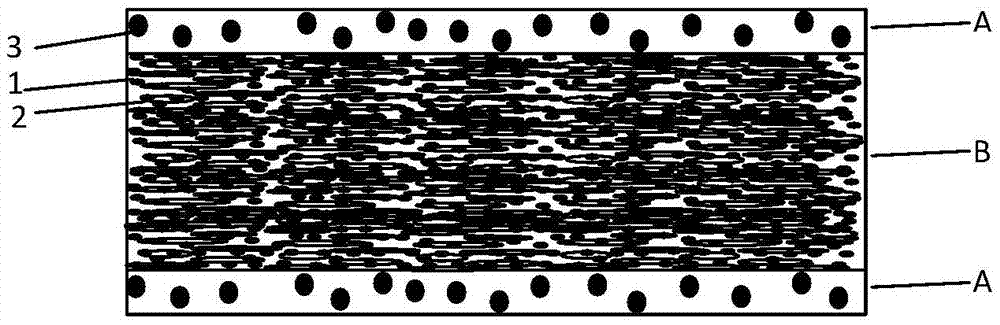
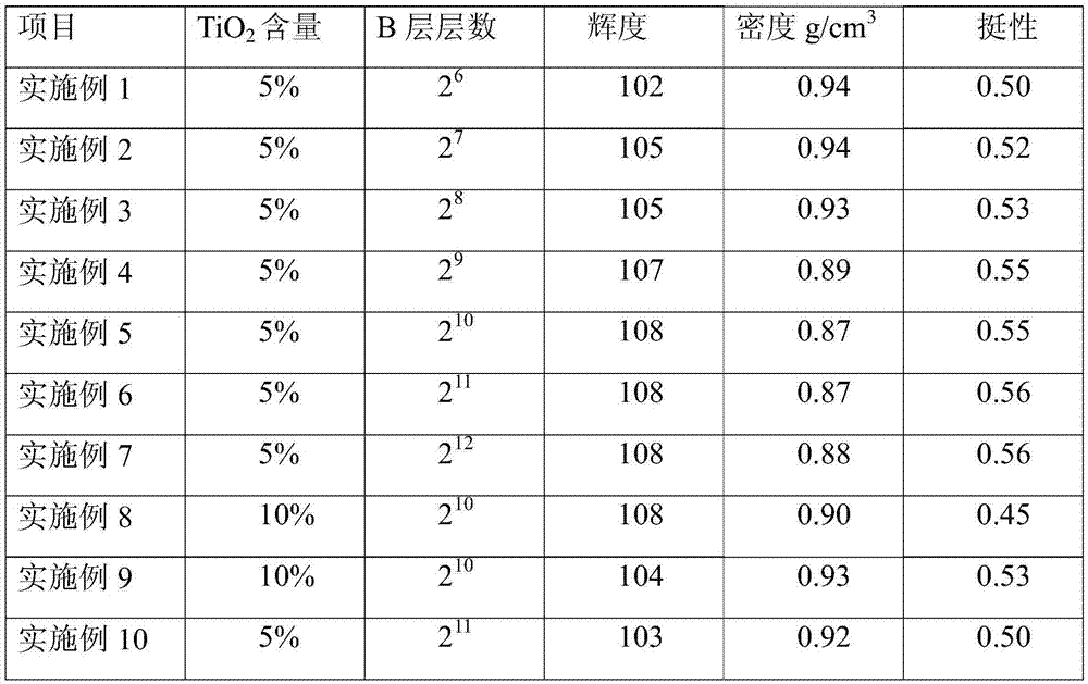
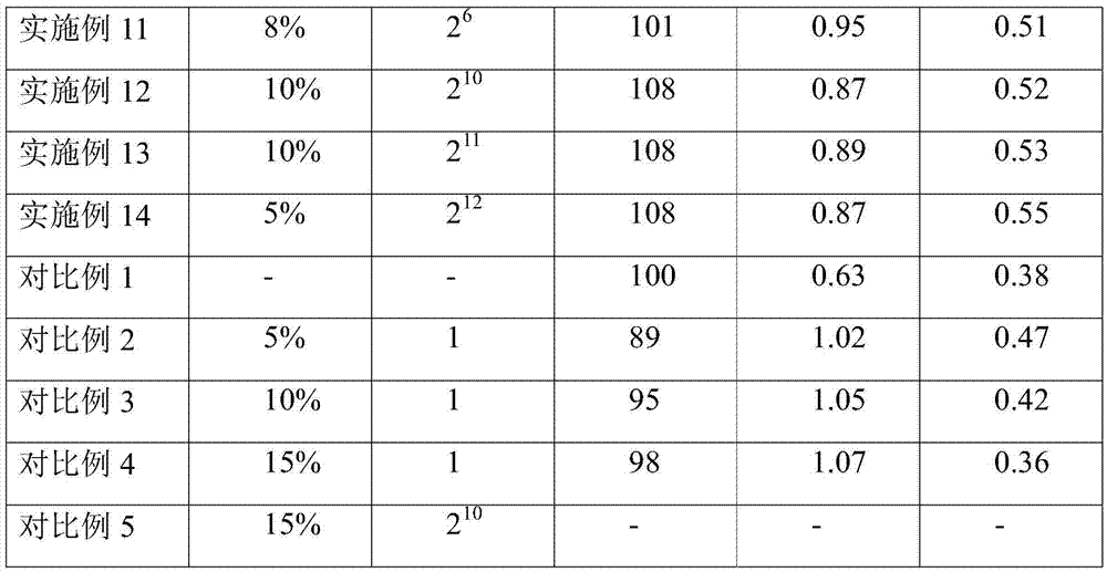
[0050] The invention provides a layered laminated reflective film, including ABA three-layer structure, A layer includes 97.7% of PET matrix resin, 2% of inorganic particle silicon dioxide, and 0.3% of quaternary ammonium salt type cationic antistatic agent, silicon dioxide The particle size is 3 μm. Layer B includes 80% of PET matrix resin, 15% of incompatible resin polymethylpentene, and 5% of white inorganic filler titanium dioxide, and the particle size of titanium dioxide is 0.3 μm. The melt of the B-layer formula passes through 6 splitter units, and merges with the A-layer formula melt in the adapter to enter the die casting sheet, and then stretches longitudinally and transversely to produce a reflective film. The thickness of the reflective film is controlled at 188μm , the B layer accounts for 90% of the total thickness, and the two A layers account for 10%. The B layer has 2 6 a layered structure.

Embodiment 2

[0052] For the layered laminated reflective film provided in Example 1, wherein, the melt of the B-layer formula passes through 7 splitter units, and merges with the A-layer formula melt in the adapter to enter the die casting sheet, and then passes through the longitudinal and transverse directions. The reflective film was stretched to obtain a thickness of 188 μm, the B layer accounted for 90% of the total thickness, and the two A layers accounted for 10% in total. The B layer has 2 7 a layered structure.

Embodiment 3

[0054] For the layered laminated reflective film provided in Example 1, wherein, the melt of the B-layer formula passes through 8 splitter units, and merges with the A-layer formula melt in the adapter to enter the die casting sheet, and then passes through the longitudinal and transverse directions. The reflective film was stretched to obtain a thickness of 188 μm, the B layer accounted for 90% of the total thickness, and the two A layers accounted for 10% in total. The B layer has 2 8 a layered structure.


PUM

PropertyMeasurementUnit
thicknessaaaaaaaaaa
particle diameteraaaaaaaaaa
glass transition temperatureaaaaaaaaaa

Abstract

The invention relates to the technical field of optical thin film, in particular to a reflecting film applied in a backlight system with a liquid-crystal display as well as a manufacturing method thereof. In order to solve the problems of low brightness and low stiffness in the existing optical thin film, the invention provides a laminated composite reflecting film and a manufacturing method thereof. The reflecting film is of an ABA-type three-layer co-extrusion structure, wherein the layer B is provided with several stratified structures. Moreover, the layer A is prepared from, by weight, 78%-98.9% of matrix resin, 1%-20% of inorganic particle and 0.1%-2% of antistatic agent, meanwhile, the layer B is prepared from, by weight, 70%-90% of matrix resin, 5%-20% of incompatible resin and 5%-10% of white inorganic stuffing. The laminated composite reflecting film has the advantages of great brightness, good stiffness and less production cost due to less content of white inorganic pigments.

Description

technical field [0001] The invention relates to the technical field of optical thin films, in particular to a high-efficiency reflective film applied to a liquid crystal display backlight source system and a manufacturing method thereof. Background technique [0002] The reflective film is a part of the material of the LCD backlight module. It is located at the bottom of the backlight module and under the light guide plate. Its function is to reflect the light leaked through the light guide plate and return to the panel side. , to reduce light loss and increase brightness. [0003] Liquid crystal display technology (LCD) is one of the most widely used display technologies at present, and will occupy the mainstream technology position in the field of flat panel display for a period of time. The liquid crystal molecule itself does not emit light. The image or character it displays is the result of its modulation of the light emitted by the backlight. The backlight is an impor...

Claims


Application Information

Patent Timeline
Patent Type & Authority Applications(China)
IPC IPC(8): G02F1/13357G02B5/08G02B1/10
CPCG02B1/10G02B5/0808G02F1/133605
Inventor 金亚东朱小玺
Owner NINGBO CHANGYANG TECH
Why Eureka
Try Eureka