Vehicle extinguishing system

A technology for fire extinguishing systems and vehicles, applied in fire rescue and other directions, can solve problems such as affecting the performance of nozzles, missing the best time for fire extinguishing, blocking people's sight, etc. Effect

Pending Publication Date: 2017-07-07
航天康达(北京)科技发展有限公司
View PDF8 Cites 7 Cited by
  • Summary
  • Abstract
  • Description
  • Claims
  • Application Information

AI Technical Summary

Problems solved by technology

However, the fire extinguishing system is manually controlled by the driver, and the driver may miss the best time to extinguish the fire while driving the vehicle; at the same time, because the water is sprayed through the water pump and the sprinkler head, the fire extinguishing speed and efficiency are very low, and the requirements for rapid fire extinguishing cannot be met.
[0004] In addition, the dry powder fire extinguishing agent equipped with large vehicles may enter the respiratory tract of escaped personnel after spraying, and block people's sight, thus causing further harm.
The green and environmentally friendly water mist fire extinguishing system has the disadvantage of high water quality requirements, because if the water quality is poor, it will cause nozzle blockage, which will not only affect the performance of the nozzle, but also cause damage to the nozzle
In addition, compared with some gas fire extinguishing systems, the water mist system takes a longer time to extinguish the fire
And it is not suitable for some objects that will react strongly with water
At the same time, the automatic fire extinguishing device currently equipped on the car may have failed after several years of installation, but the driver does not know it, and eventually loses the opportunity to extinguish the fire

Method used


Image

  • Vehicle extinguishing system
  • Vehicle extinguishing system
  • Vehicle extinguishing system

Examples


Embodiment Construction

[0032] The specific implementation manners of the present invention will be further described in detail below in conjunction with the accompanying drawings and embodiments. The following examples are only used to illustrate the present invention, but are not used to limit the protection scope of the present invention.

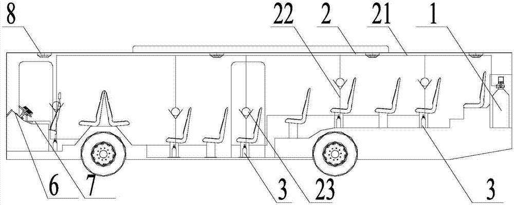
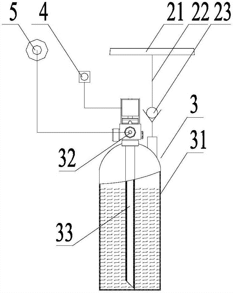
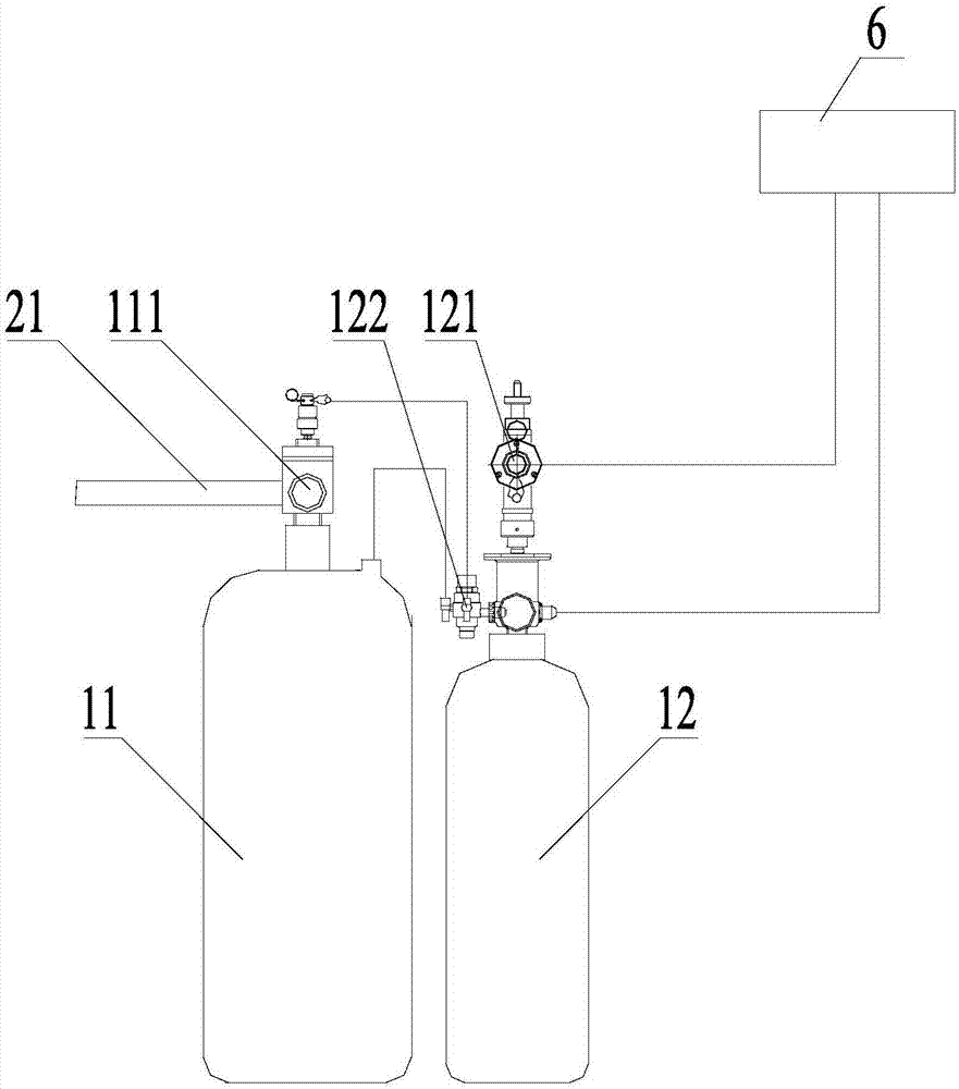
[0033] The vehicle fire extinguishing system of the present invention comprises: a fire extinguishing agent storage and driving bottle set 1, a delivery pipeline 2 and a plurality of local pressure storage bottles 3; the fire extinguishing agent storage and driving bottle set 1 includes driving gas and fire extinguishing agent; the delivery pipeline 2 It includes a conveying main pipe 21 and a plurality of conveying branch pipes 22 with one-way valves 23 respectively. Each conveying branch pipe 22 is connected to the conveying main pipe 21 in parallel. The outlet end of the local pressure storage bottle 3 is connected to the inlet end; the outlet end of the loc...


PUM


Abstract

The invention discloses a vehicle extinguishing system which comprises an extinguishant storage and drive bottle set, a conveying pipeline and a plurality of local pressure storage bottles. The conveying pipeline comprises a conveying main pipe and a plurality of conveying branched pipes separately provided with one-way valves. All the conveying branched pipes are in parallel connection with the conveying main pipe. The inlet end of the conveying main pipe is connected with the extinguishant storage and drive bottle set. The outlet ends of all the conveying branched pipes are connected with the inlet ends of the local pressure storage bottles, and the outlet ends of the local pressure storage bottles are connected with starting buttons and atomizing spray heads. According to the vehicle extinguishing system, through the method that the extinguishant storage and drive bottle set is combined with the local pressure storage bottles, when a local fire occurs, the local pressure storage bottles are manually opened to put out the local fire, and when a fire is severe, the extinguishant system is fully started to rapidly control fire deterioration, the purposes of local extinguishing and overall extinguishing are simultaneously achieved, and the adaptability is high. The vehicle extinguishing system is reasonable in structural arrangement, small in occupied space, easy to mount and wide in application prospect.

Description

technical field [0001] The present invention relates to the technical field of fire protection, and more specifically, to a vehicle fire extinguishing system. Background technique [0002] With the continuous acceleration of the urbanization process in our country, the urban population has increased rapidly, and the urban traffic has become increasingly congested. After years of hard work, most cities in our country have built a convenient and fast bus system with wide coverage. However, the current bus system in most cities in my country only meets the basic problem of whether people have cars or not, and has not been able to provide a better ride environment and formulate and implement a sound safety management system, leaving certain hidden dangers. In recent years, public transport, especially urban bus fire accidents have occurred frequently, exposing serious hidden dangers in the current public transport management system and fire safety measures in some areas of our c...

Claims


Application Information

Patent Timeline
Patent Type & Authority Applications(China)
IPC IPC(8): A62C3/07
CPCA62C3/07
Inventor 苗广州
Owner 航天康达(北京)科技发展有限公司
Why Eureka
Try Eureka