
Metal chemical mechanical polishing slurry

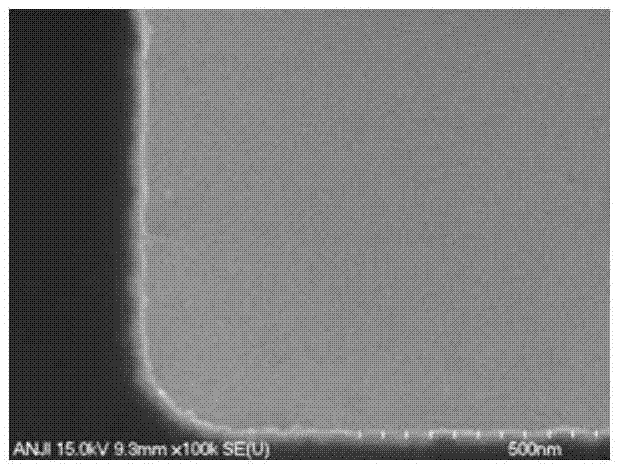
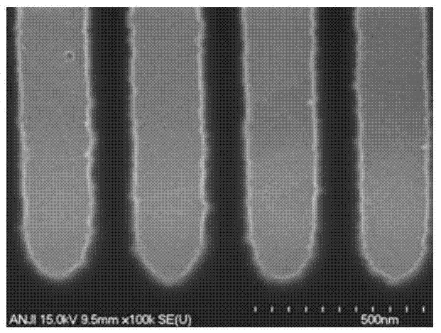
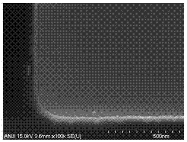
A chemical mechanical and polishing slurry technology, which is applied in the field of chemical mechanical polishing slurry, can solve the problems of large dish-shaped depressions of copper wires, narrow over-polishing windows, and inconspicuous effects, and achieve reduced butterfly-shaped depressions, high copper removal rate, Improved performance of overthrown windows

Inactive Publication Date: 2017-07-07
ANJI MICROELECTRONICS TECH (SHANGHAI) CO LTD
View PDF8 Cites 9 Cited by
  • Summary
  • Abstract
  • Description
  • Claims
  • Application Information

AI Technical Summary

Problems solved by technology

The above-mentioned patent overcomes the problems encountered in the polishing process of the above-mentioned copper to a certain extent, but the effect is not obvious. The problem of narrow polishing window; the polishing rate is not high enough to be applied to the process that requires high removal rate

Method used


Image

  • Metal chemical mechanical polishing slurry
  • Metal chemical mechanical polishing slurry
  • Metal chemical mechanical polishing slurry

Examples


Embodiment 1~49

[0033] Table 1 shows Examples 1-49 of the chemical mechanical polishing solution of the present invention. According to the formula given in the table, the other components except the oxidizing agent are mixed evenly, and the mass percentage is made up to 100% with water. with KOH or HNO 3 Adjust to desired pH. Add oxidant before use and mix evenly.

[0034] Table 1 Examples 1-49

[0035]

[0036]

[0037]

[0038]

[0039]

[0040]

[0041]


PUM

PropertyMeasurementUnit
particle diameteraaaaaaaaaa
specific surface areaaaaaaaaaaa

Abstract

The invention provides a slurry used for copper chemical mechanical polishing and application thereof. The slurry comprises: (a) grinding particles, (b) complexing agents, (c) oxidants, (d) corrosion inhibitors, and (e) phosphate ester surface active agents. The use of the slurry provided in the invention can maintain a high removal rate of copper and improve the defects such as butterfly recesses and over-throwing windows of the polished copper wire, and the polished copper surface has few contaminants and no corrosion.

Description

technical field [0001] The invention relates to a chemical mechanical polishing slurry and its application, in particular to a chemical mechanical polishing slurry for copper and its application. Background technique [0002] With the development of semiconductor technology and the miniaturization of electronic components, an integrated circuit contains millions of transistors. The operation process integrates such a large number of transistors that can switch rapidly. The use of traditional aluminum or aluminum alloy interconnection wires will reduce the signal transmission speed and consume a lot of energy in the process of current transmission. This also hinders semiconductors in a certain sense. technology development. For further development, people began to look for materials with higher electrical properties to replace the use of aluminum. As we all know, copper has low resistance and good conductivity, which speeds up the signal transmission speed between transisto...

Claims


Application Information

Patent Timeline
Patent Type & Authority Applications(China)
IPC IPC(8): C23F3/06C23F3/04
CPCC23F3/04C23F3/06
Inventor 张建荆建芬宋凯蔡鑫元杨俊雅潘依君
Owner ANJI MICROELECTRONICS TECH (SHANGHAI) CO LTD
Learn More