Unpowered rainfall runoff pollutant intercepting facility and pollutant intercepting operation method

A pollutant and rainwater technology, applied in water/sludge/sewage treatment, drainage structures, water/sewage treatment, etc., to achieve the effect of improving effluent quality

Inactive Publication Date: 2017-07-07
TIANJIN WATER RESOURCES RES INST
View PDF4 Cites 7 Cited by
  • Summary
  • Abstract
  • Description
  • Claims
  • Application Information

AI Technical Summary

Problems solved by technology

[0003] The main purpose of the present invention is to solve the problems in the above-mentioned rainwater sewage inte

Method used


Image

  • Unpowered rainfall runoff pollutant intercepting facility and pollutant intercepting operation method
  • Unpowered rainfall runoff pollutant intercepting facility and pollutant intercepting operation method
  • Unpowered rainfall runoff pollutant intercepting facility and pollutant intercepting operation method

Examples


Embodiment 1

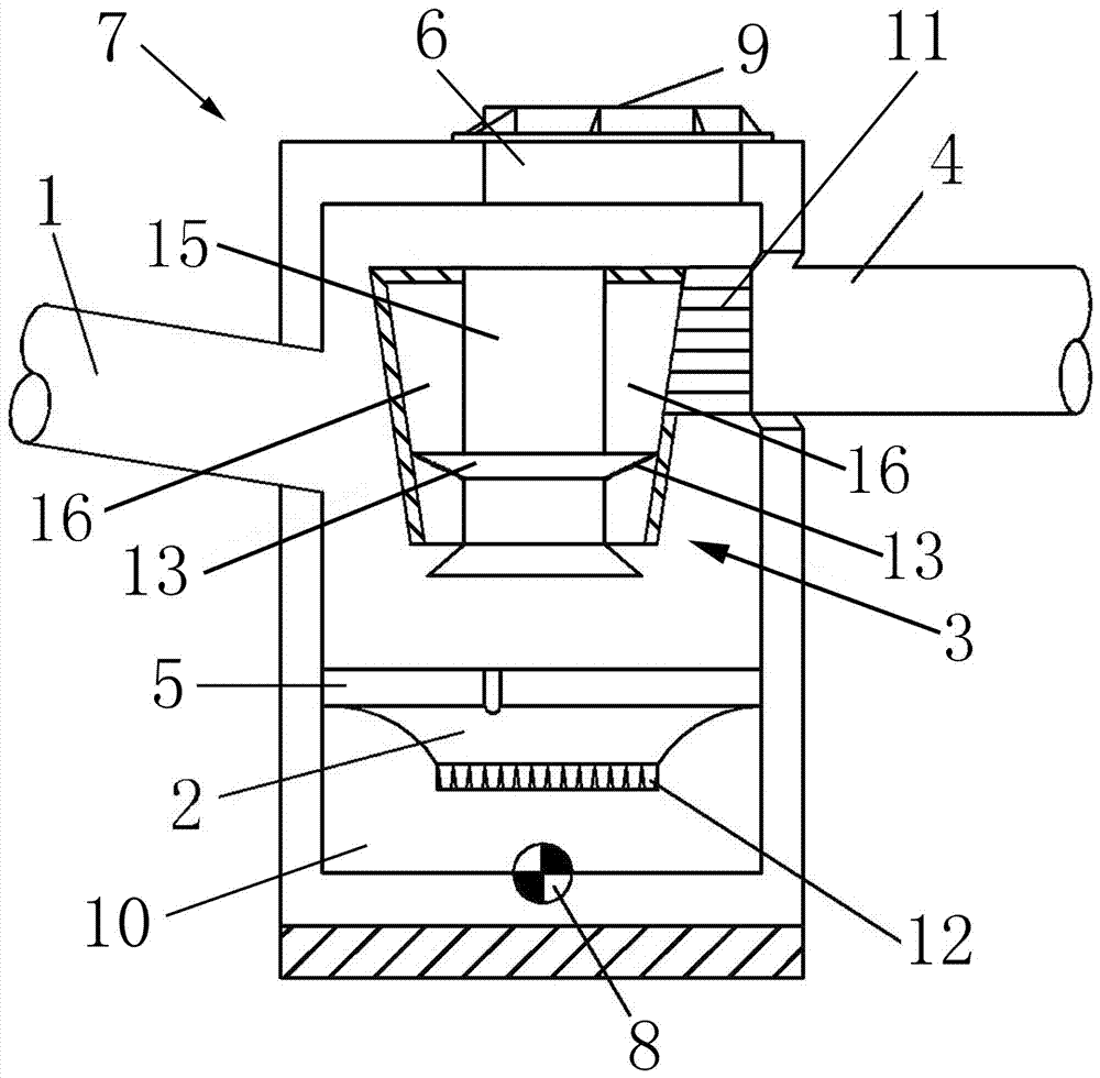
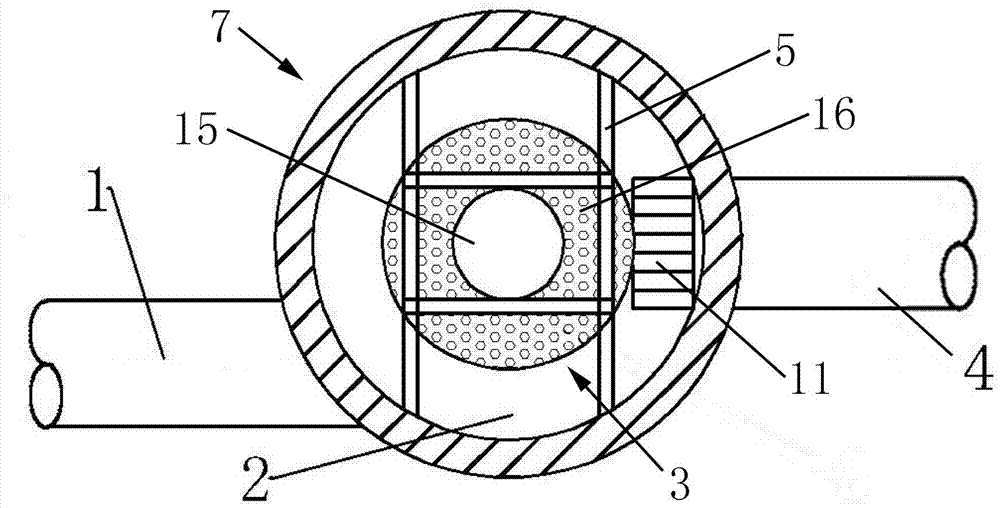
[0024] It consists of the main body of the facility (7), the water inlet pipe (1), the water outlet pipe (4), the guide tube (3), the guide plate (2), the sediment collection area (10), the water outlet collection port (11), the slag discharge The main body of the facility (7) is barrel-shaped as a whole, and the main body of the facility (7) is made of cement products, cast iron or modified plastic materials, and water inlet pipes (1) are arranged on both sides of the upper part of the main body of the facility (7). and the water outlet pipe (4), the water inlet pipe (1) and the water outlet pipe (4) are connected with the main body (7) of the facility, the water inlet pipe (1) and the water outlet pipe (4) are made of metal or modified plastic material, and the facility The water inlet pipe (1) is installed on one side of the main body (7), and the water inlet pipe (1) is inserted into the facility main body (7) at an oblique angle, and the water inlet pipe (1) is inserted in...

Embodiment 2

[0026] A support frame (5) is set in the middle of the main body (7) of the facility, and the support frame (5) is in the shape of a well as a whole, and a guide tube (3) is installed on the support frame (5), and the guide tube (3) is in the shape of a barrel as a whole , the guide tube (3) is made of metal material or modified plastic material, the guide tube (3) is composed of the guide tube inner tube (15) and the guide tube outer tube (16), the guide tube outer tube (16 ) barrel, the whole is a blind hole, the inner tube of the guide tube (15) is packed in a barrel, and the whole is a through hole, one end of the inner tube of the guide tube (15) passes through the upper end of the outer tube of the guide tube (16), and the guide tube The other end of the inner tube of the flow tube (15) passes through the lower end of the outer tube of the flow guide tube (16), and the top end of the other end of the inner tube of the flow guide tube (15) is funnel-shaped, and the top of ...

Embodiment 3

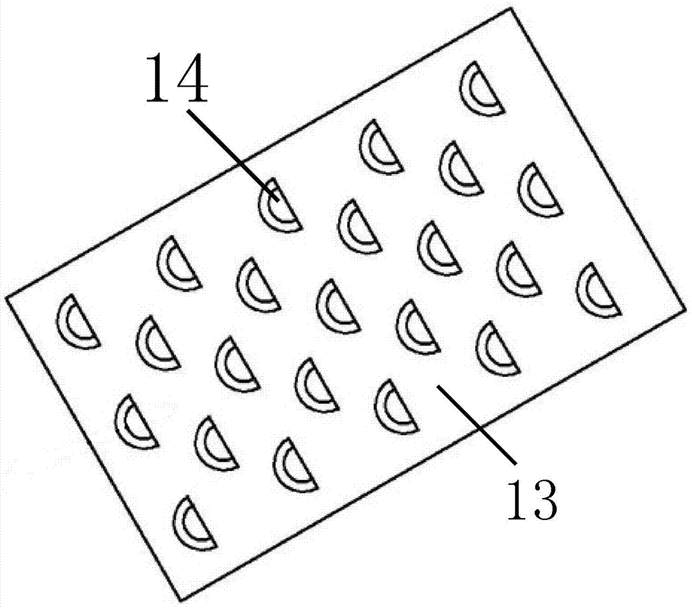
[0029] The rainwater passes through the filter screen (13) during the rising process, and the residual pollutants are intercepted. The rainwater passes through the sieve holes (14) of the filter screen (13) and swirls up in the outer cylinder (16) of the diversion cylinder. The other side of the main body (7) is provided with a water outlet pipe (4), and one end of the water outlet pipe (4) is provided with a water outlet collection port (11). 18) is fixedly connected to the cylinder wall, and one end of the water outlet pipe (4) is provided with a water outlet collection port (11), and the water outlet collection port (12) is connected with the upper part of the diversion outer cylinder (18), and passes through the filter screen (13 ) through the water outlet collection port (11) to collect the rainwater in the diversion outer cylinder (18), and the separated rainwater flows into the outlet pipe (4) to be discharged. The cover plate (9) can carry out inspection or maintenance...


PUM


Abstract

The invention provides an unpowered rainfall runoff pollutant intercepting facility and a pollutant intercepting operation method. A facility main body is barrel-shaped in the whole, a water inlet pipe and a water outlet pipe are mounted at two sides of the upper part of the facility main body, respectively, the water inlet pipe is inserted into the facility main body in the form of an inclination angle and is connected with the circumferential tangent insertion inner wall of the facility main body, a flow guide barrel is mounted on a support frame in the facility main body, rainwater forms the vortex state between the inner wall of the facility main body and the flow guide barrel, then centrifugal force is generated, sundries in the rainwater fall into a sediment collecting area from a lower leaking hole of a flow guide plate, then a deslagging hole is opened, and the sundries are discharged. The unpowered rainfall runoff pollutant intercepting facility is simple in structure, good in reliability, and simple and convenient to mount and maintain, through the improvement on the original initial rainwater pollutant intercepting facility, the intercepting and processing efficacies for the rainfall runoff pollutants are improved, the improved facility main body is integrated, and is convenient to mount and overhaul, and only regular checking, desilting and pollutant discharge are needed.

Description

technical field [0001] The invention relates to an improved initial rainwater interception device, in particular to a sewage interception facility for unpowered rainwater runoff pollutants and a sewage interception operation method. Background technique [0002] China is one of the most water-scarce countries in the world. my country is rich in rainwater resources, and the collection and utilization of rainwater has become particularly important. Due to the serious pollution of the initial rainwater, it cannot be directly discharged into the receiving water body. At present, most of the initial rainwater interception devices can only simply intercept suspended solids, oil pollution and other pollutants in the initial rainwater, and the treatment efficiency is not high, especially for pollutants with small particle sizes, and the initial rainwater carries a large amount of air. Pollutants in and on the ground. Contents of the invention [0003] The main purpose of the pre...

Claims


Application Information

Patent Timeline
IPC IPC(8): E03F1/00E03F5/00E03F5/14E03B3/02
CPCE03B3/02E03F1/00E03F5/00E03F5/14Y02A20/108
Inventor 常素云占强吴涛许伟李岩
Owner TIANJIN WATER RESOURCES RES INST
Why Eureka
Try Eureka