Relay control module, control method thereof and relay control system

A relay control and relay technology, applied in the field of electronics, can solve the problems of unsafe communication, single control method, and narrow application area, and achieve the effect of solving unsafe communication and expanding the application area.

Pending Publication Date: 2017-07-07
徐坚
View PDF6 Cites 6 Cited by
  • Summary
  • Abstract
  • Description
  • Claims
  • Application Information

AI Technical Summary

Problems solved by technology

[0003] In view of this, the purpose of the embodiments of the present invention is to provide a relay control module, its control method and a relay con

Method used


Image

  • Relay control module, control method thereof and relay control system
  • Relay control module, control method thereof and relay control system
  • Relay control module, control method thereof and relay control system

Examples


no. 1 example

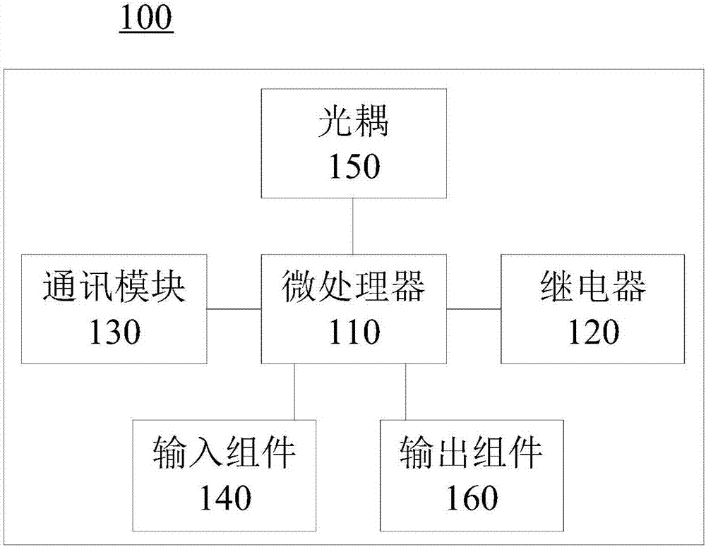
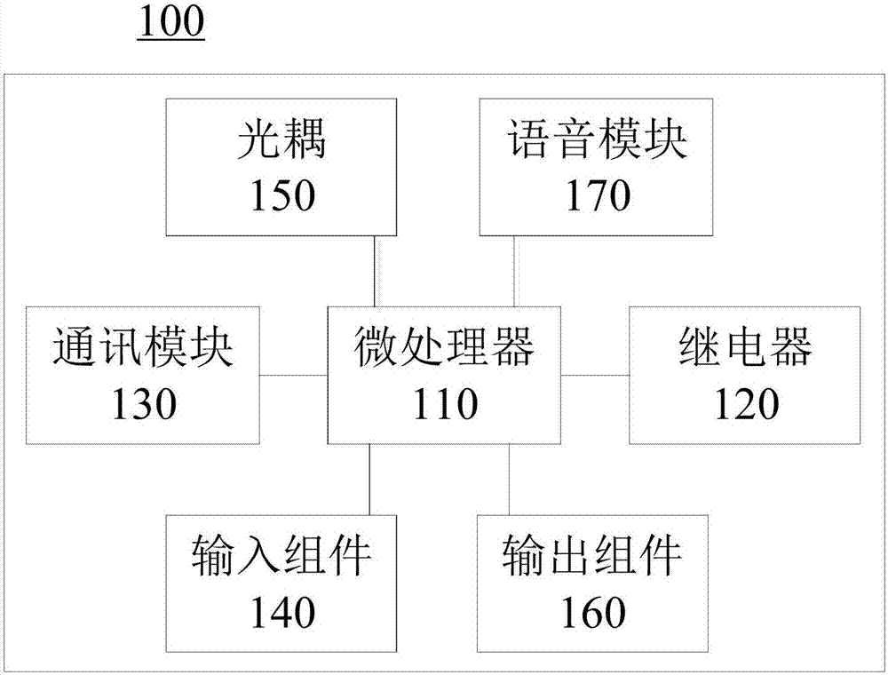
[0019] Please refer to figure 1 , the first embodiment of the present invention provides a relay control module 100 , which includes a microprocessor 110 , a relay 120 , a communication module 130 , an input component 140 , an optocoupler 150 and an output component 160 . The microprocessor 110 is respectively coupled with the relay 120 , the communication module 130 , the input component 140 , the optocoupler 150 and the output component 160 .

[0020] Wherein, the relay 120 is also called an electric relay, which is an electronic control device. It has a control system (also known as input circuit) and a controlled system (also known as output circuit), which is usually used in automatic control circuits, and is an "automatic switch" that uses smaller currents to control larger currents. As an implementation manner, the same relay control module 100 may include multiple relays 120 , and each relay 120 is coupled to the microprocessor 110 respectively. Relays 120 with the s...

no. 2 example

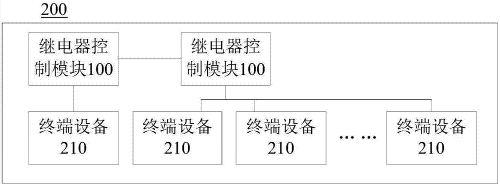
[0065] Please refer to image 3 , the second embodiment of the present invention provides a relay control system 200 , the system includes a plurality of relay control modules 100 in the first embodiment and a plurality of terminal devices 210 . Each of the relay control modules 100 is electrically connected to one or more terminal devices 210 , and a communication connection between multiple relay control modules 100 can be realized through the communication module 130 .

[0066] The terminal devices 210 may be the same or different. Different terminal devices 210 may provide different signal inputs. For example, it can be elevator signal, electromagnetic lock signal, DC motor signal, newspaper box or locker signal, pure water machine signal, hall lighting signal, door magnetic signal, human body infrared signal, light sensor signal, etc. It can be applied to automatic curtain or street lamp control by connecting light sensing signal and time judgment; it can be applied to ...

no. 3 example

[0080] Please see Figure 5 , the third embodiment of the present invention provides a control method for a relay control module, and the method is applied to the relay control module in the first embodiment. The following will be Figure 5 As illustrated in the flow chart, the method includes:

[0081] Step S110: the communication module receives control parameters.

[0082] Step S120: the input component collects signal data.

[0083] Step S130: the microprocessor judges whether the signal data satisfies a preset condition.

[0084] Step S140: When the preset condition is satisfied, the microprocessor drives the relay and the terminal device connected to the output component to work according to the preset program based on the control parameter.

[0085] The preset program includes: a virtual signal obtained by calculating a logical variable according to a preset logical expression, and the virtual signal is used to control the relay, wherein the logical variable is an i...


PUM


Abstract

The present invention provides a relay control module, a control method thereof and a relay control system and relates to the electronic field. The relay control module comprises a microprocessor, a relay, a communication module, an input assembly and an output assembly. The microprocessor is respectively coupled to the relay, the communication module, the input assembly and the output assembly. The communication module is used for receiving and/or sending modifiable control parameters. The input assembly is used for acquiring signal data. The microprocessor is used for storing an encryption algorithm and a secret key matched with the encryption algorithm. The microprocessor is also used for encrypting control parameters based on the encryption algorithm and then sending the control parameters to the communication module, or decrypting the control parameters received by the communication module based on the secret key. The relay control module can alleviate the problem in the prior art that a current relay control module is single in control mode, narrow in application range and unsafe in communication.

Description

technical field [0001] The invention relates to the field of electronics, in particular to a relay control module, its control method and a relay control system. Background technique [0002] The relay (Relay), also known as the relay, is an electronic control device, which has a control system (also known as the input circuit) and a controlled system (also known as the output circuit), usually used in automatic control circuits, and is used in small A kind of "automatic switch" that controls the larger current. The traditional relay integrated control module only controls one or a group of relays each time, and the single control method has a narrow application area, and the communication is not safe. Contents of the invention [0003] In view of this, the purpose of the embodiments of the present invention is to provide a relay control module, its control method and a relay control system, so as to alleviate the problems of single control mode, narrow application area a...

Claims


Application Information

Patent Timeline
IPC IPC(8): G05B19/042
CPCG05B19/0425G05B2219/25252G05B2219/25242G05B2219/24167
Inventor 徐坚郭萍徐一帆
Owner 徐坚
Why Eureka
Try Eureka