
Push-rod high-power electromagnetic relay

An electromagnetic relay, high-power technology, applied in electromagnetic relays, electromagnetic relay details, relays, etc., can solve the problems of small electromagnetic system space, ablated contacts, and large contact reaction force, and increase insulation performance. , the effect of reducing the elastic coefficient and ensuring reliability

Active Publication Date: 2017-07-07
宁波华仑电子有限公司
View PDF9 Cites 2 Cited by
  • Summary
  • Abstract
  • Description
  • Claims
  • Application Information

AI Technical Summary

Problems solved by technology

[0003] The size of the mounting pins of the relay is generally determined according to the requirements of use, and is usually a standard size. For example, the size of the pins of many relays is a multiple of 2.54 when converted from the imperial system to the metric system. Therefore, the design of the relay product structure will be affected by the pins of the relay. The impact of the installation size of the bit, such as the structure and size of the components in the relay, and then affect the technical indicators of the relay, under the conditions of the limited external dimensions and the distance between the pins of the relay, there are two types of existing electromagnetic relays The first is that the space of the electromagnetic system is small, so the driving source of the electromagnetic relay is relatively small, and the contact load conversion capacity of the relay is relatively small, which cannot meet the requirements of users; the second is that although the volume of the electromagnetic system is increased , but because the driving force of the electromagnetic system is relatively large, the contact contact force is also relatively large when the contacts are closed, and the frequency and amplitude of the contact bounce caused by the moving contacts will increase, and the contacts are easy to contact. The arc is generated and the contact is ablated, which causes the relay to fail after the contact has been operated for many times. What is more, the contact cannot be closed and produce substandard products on the relay production line.

Method used


Image

  • Push-rod high-power electromagnetic relay
  • Push-rod high-power electromagnetic relay
  • Push-rod high-power electromagnetic relay

Examples


Embodiment 1

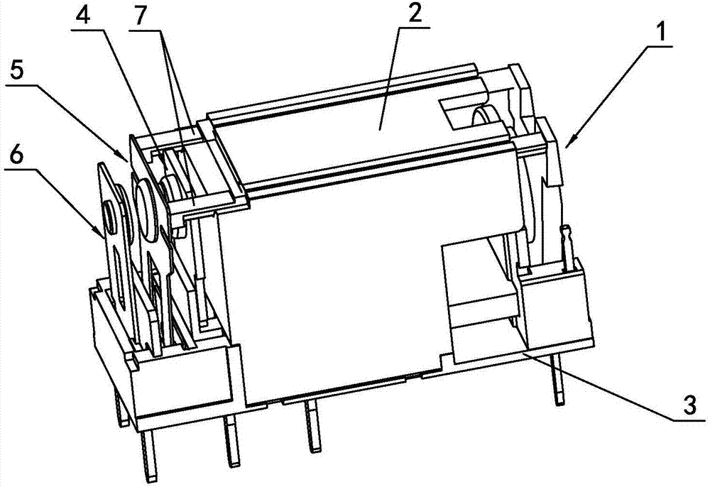
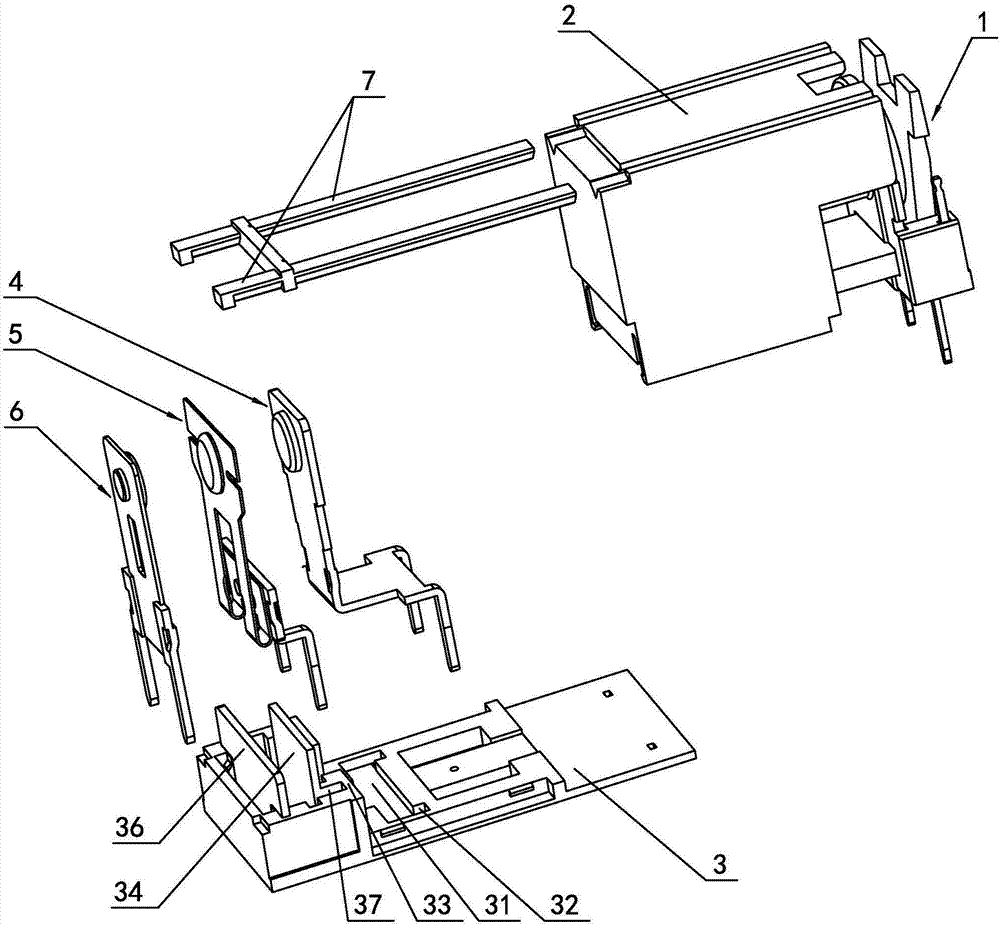
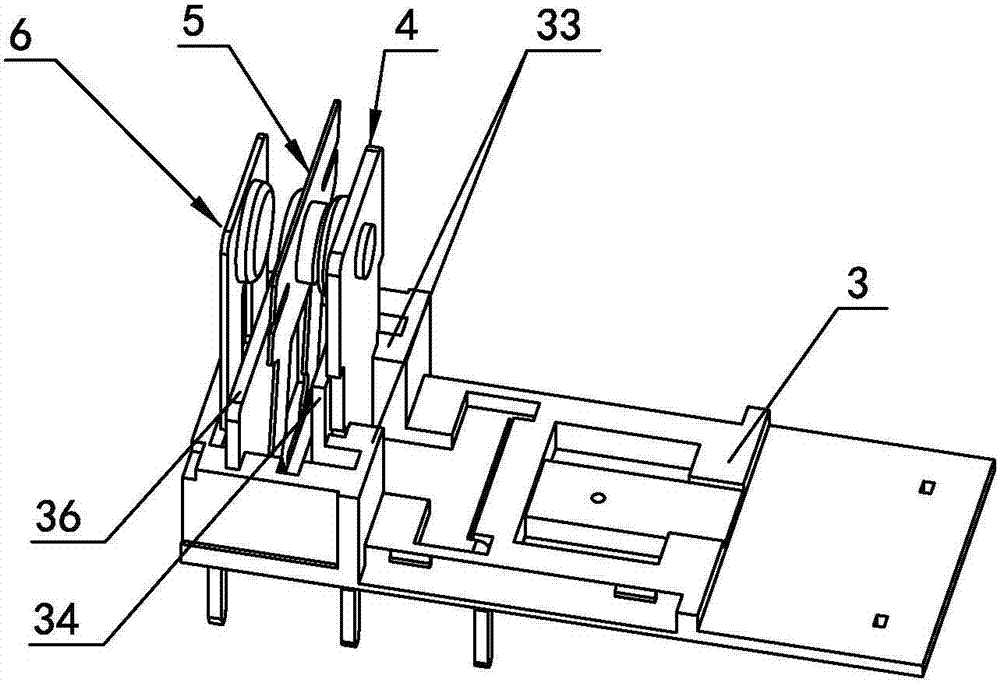
[0026] Embodiment one, such as Figure 1 to Figure 8 As shown, a push rod type high-power electromagnetic relay includes an electromagnetic system 1, an insulating cover 2, a base 3, and a normally closed static contact group 4 fixedly arranged on the base 3 from near to far from the electromagnetic system 1, The dynamic contact group 5 and the normally open static contact group 6, the electromagnetic system 1 is installed in the insulating cover 2, the normally closed static contact group 4 includes a static contact piece 41 and a normally closed static contact point 42 arranged on the upper part of the normally closed static contact piece 41 , the normally closed static contact piece 41 is a straight plate type, and its lower end is integrally provided with a first bending part 411 and two normally closed static lead-out pins 412 connected with the first bending part 411, and the dynamic contact group 5 includes an upper part provided with The movable reed 52 of the movable ...

Embodiment 2

[0029] Embodiment two, such as Figures 9 to 10 As shown, the technical features are the same as those in Embodiment 1, the difference is that the relay is a group of normally closed forms, that is, the normally open static contact piece 61 of the normally open static contact group 6 is not provided with a normally open static lead-out pin 63, and the normally open The material of static contact 62 also can be made of ordinary metal material instead of precious metal material, in addition, because of dustproof or sealing requirements, it also includes casing 8, and the bottom of base 3 is provided on two opposite sides below insulating cover 1. There are a plurality of small grooves 38, and the case 8 is fixedly connected to the base 3. The inner side wall of the case 8 and the small grooves 38 form a small slot 39. In this way, when the relay is in the sealing process, a small amount of glue is released from the small groove. The hole 39 flows in, so that the connection betwe...


PUM


Abstract

The invention discloses a push-rod high-power electromagnetic relay which comprises an electromagnetic system, an insulating hood, a base, a normally closed static contact group, a movable contact group and a normally open static contact group, wherein the normally closed static contact group, the movable contact group and the normally open static contact group are fixedly arranged on the base in a near-far sequence from the electromagnetic system. The electromagnetic relay is characterized in that a first bending part and at least one normally closed static leading pin connected with the first bending part are arranged at the lower end of a normally closed static contact piece; a first clamping groove used for correspondingly clamping the first bending part and a first inserting groove used for correspondingly inserting the normally closed static leading pins are formed in the base; the first bending part is completely clamped into the first clamping groove; the insulating hood is arranged above the first bending part of the static contact piece, and fixedly connected with the base; and first strip groove holes are symmetrically formed on the left side and the right side of the upper part of a movable spring. The electromagnetic relay has the advantages that the load transfer capacity of contact points can be improved to the greatest extent under the condition that a boundary dimension of the electromagnetic relay and mounting dimensions of the leading pins are defined; and a good insulating property and reliable contact of the contact points can be ensured.

Description

technical field [0001] The invention relates to an electromagnetic relay, in particular to a push rod type high-power electromagnetic relay. Background technique [0002] The relay is a widely used electronic component, which is widely used in household appliances, automobiles, industrial control, power systems, communication devices and other fields. The development of miniaturization and high power of electromagnetic relays requires one of its development directions. [0003] The size of the mounting pins of the relay is generally determined according to the requirements of use, and is usually a standard size. For example, the size of the pins of many relays is a multiple of 2.54 when converted from the imperial system to the metric system. Therefore, the design of the relay product structure will be affected by the pins of the relay. The impact of the installation size of the bit, such as the structure and size of the components in the relay, and then affect the technical...

Claims


Application Information

Patent Timeline
Patent Type & Authority Applications(China)
IPC IPC(8): H01H50/02H01H50/54H01H50/56H01H50/58
CPCH01H50/02H01H50/54H01H50/56H01H50/58H01H2050/028
Inventor 杨晓厦高国章王水君
Owner 宁波华仑电子有限公司
Learn More