

Bionic intervertebral fusion cage
A technology of intervertebral fusion device and fusion device, which is applied in the field of bionic intervertebral fusion devices, can solve the problem of multi-level porous material properties such as uneven strength and elastic modulus, which cannot meet the functional requirements of bionic bone restorations, and cannot be truly and effectively controlled Hole size and other issues at all levels, to achieve the effect of being conducive to bearing external force, large friction force, and simplified structure
- Summary
- Abstract
- Description
- Claims
- Application Information
AI Technical Summary
Problems solved by technology
Method used
Image

Examples
Embodiment 1
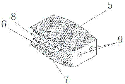
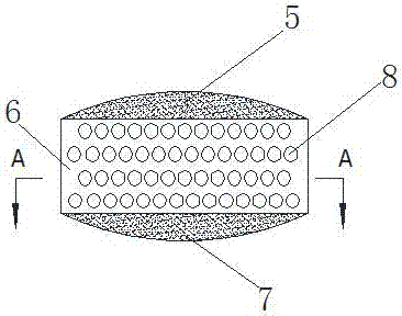
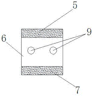
[0029] As attached Figure 1-4 As shown, a bionic intervertebral fusion cage includes a cage body; the cage body is divided into three layers: an upper part 5, a middle part 6 and a lower part 7; the upper end face of the upper part 5 and the lower end face of the lower part 7 are convex curved surfaces The two opposite sides of the middle part 6 are provided with multiple rows of staggered through holes 8, and the middle part 6 is provided with two clamping holes 9 on the other two opposite sides adjacent to the side face with the through holes 8 , And the clamping holes 9 are intersected with two adjacent rows of through holes 9 located in the middle of the multiple rows of staggered through holes 8; the upper part 5 and the lower part 7 are made of porous tantalum material with an average pore diameter of 400-1000 μm, The porosity is 60-80%; the middle part 6 of the cage body is made of a dense medical metal material titanium alloy, and after electron beam melting, the fixed ...
Embodiment 2
[0031] A bionic intervertebral fusion cage, the structure of which is the same as that of the bionic intervertebral fusion cage described in Example 1. The difference between the two is only that the upper part 5 and the lower part 7 of the bionic intervertebral fusion cage in this example are composed of more Grade porous metal materials; among them, multi-grade porous metal materials such as Figure 5-7 As shown, 1 is the primary cavity, 2 is the cavity wall of the primary cavity; the cavity wall 2 of the primary cavity 1 consists of a smaller secondary cavity 3 and a cavity wall 4 surrounding the secondary cavity 3 Composition; combined with the enlarged view of the cavity wall 2 and the BB cross-sectional view, the secondary cavity 3 is three-dimensionally through; and so on, the cavity wall 4 of the secondary cavity 3 is composed of three smaller than the secondary cavity 3 The cavity and the cavity wall surrounding the tertiary cavities are formed. The tertiary cavities ar...
Embodiment 3
[0044] As attached Figure 1-4 As shown, a bionic intervertebral fusion cage includes a cage body; the cage body is divided into three layers: an upper part 5, a middle part 6 and a lower part 7; the upper end face of the upper part 5 and the lower end face of the lower part 7 are convex curved surfaces The two opposite sides of the middle part 6 are provided with multiple rows of staggered through holes 8, and the middle part 6 is provided with two clamping holes 9 on the other two opposite sides adjacent to the side face with the through holes 8 , And the clamping holes 9 are intersected with two adjacent rows of through holes 9 located in the middle of the multiple rows of staggered through holes 8; the upper part 5 and the lower part 7 are made of multi-stage porous metal material, and the middle part of the cage body 6 is made of dense medical metal material titanium alloy, and after electron beam melting, the fixed connection with the upper part 5 and the lower part 7 of t...
PUM
| Property | Measurement | Unit |
|---|---|---|
| Average pore size | aaaaa | aaaaa |
| Compressive strength | aaaaa | aaaaa |
| Elastic modulus | aaaaa | aaaaa |
Abstract
Description
Claims
Application Information