Underwater drag-reduction surface simulating scarfskin morphology of puffer and preparation method

A technology of skin and puffer fish, which is applied in the design of ship components, ships, and hulls, can solve problems such as high operating costs, layout of circuit control systems, connection constraints of electronic components, and single structure, and achieves broad industrial application prospects. The production process is diverse and the production process is reliable.

Inactive Publication Date: 2017-07-14
JIANGSU UNIV OF SCI & TECH
View PDF17 Cites 36 Cited by
  • Summary
  • Abstract
  • Description
  • Claims
  • Application Information

AI Technical Summary

Problems solved by technology

The effect of drag reduction is realized by imitating the groove shape of shark scales and the coupling effect of the secretion of drag-reducing fluid under high-speed movement of sharks. However, when this structure is used in practice, there are some problems: (1) This structure is installed on the surface of the aircraft. The shark-like skin structure contains a circuit control system inside, and its design is relatively complicated. At the same time, the layout of the circuit control system, the connection of electronic components, and the use of large-sized aircraft will be restricted; (2) to ensure The smoothness of the internal liquid storage tank and the external through hole is difficult to achieve and has no practical significance. Once the internal and external slow-release electro-hydraulic channels are blocked, the effect of secreting mucus under the high-speed motion of a shark will be lost; (3) The production cost and operating cost are relatively high. Regardless of the size of the underwater vehicle, if this drag reduction method is used, a large number of electronic components in the slow-release electro-hydraulic control system will be arranged on the surface of the vehicle. The maintenance cost is too high. Once a problem occurs in a certain part, the whole system

Method used


Image

  • Underwater drag-reduction surface simulating scarfskin morphology of puffer and preparation method
  • Underwater drag-reduction surface simulating scarfskin morphology of puffer and preparation method
  • Underwater drag-reduction surface simulating scarfskin morphology of puffer and preparation method

Examples


Embodiment Construction

[0035] The present invention will be further described below in conjunction with the accompanying drawings.

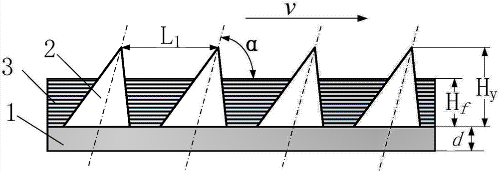
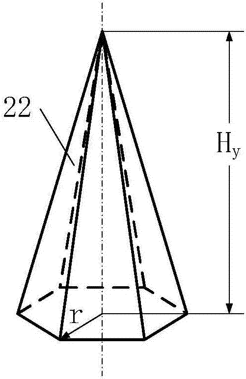
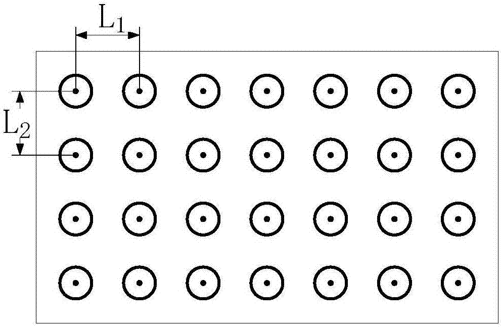
[0036] Such as figure 1 , Figure 5 and Figure 6 As shown, the underwater drag reducing surface imitating the shape of puffer fish skin according to the present invention includes a base 1 , a hard drag reducing element 2 and a flexible covering layer 3 . The base 1 can be an independent unit, such as figure 1 shown; it can be integrated with the hard drag reducing element 2, such as Figure 5 shown; it can also be integrated with the flexible covering layer 3, such as Figure 6 shown. The thickness d of the base 1 is small or it is flexible as a whole when it is integrated with the flexible covering layer 3 , while it is rigid when the thickness d is large or it is directly based on a large-sized component such as an aircraft base. The hard drag reducing element 2 is conical or columnar, has a certain hardness, and is not easy to deform. The height Hy varies in...


PUM


Abstract

The invention discloses an underwater drag-reduction surface simulating scarfskin morphology of a puffer and a preparation method. The underwater drag-reduction surface simulating the scarfskin morphology of the puffer comprises a basement, hard drag reduction elements, and soft cover layers, wherein a plurality of hard drag reduction elements are distributed on the basement, the soft cover layers are filled among the hard drag reduction elements, and the hard drag reduction elements are tightly attached to the joint surface of the basement and the hard drag reduction elements. By adoption of the tapered or columnar hard drag reduction elements, the underwater drag-reduction surface simulating the scarfskin morphology of the puffer is different from the existing rib-shaped groove structure; and the soft layers are covered on the basement and form the rigid-flexible drag reduction surface which can form adaptive variations with differences of water velocity on the surface and fit with the scarfskin properties of the puffer better.

Description

technical field [0001] The invention relates to an underwater drag-reducing surface imitating the shape of puffer fish skin and a manufacturing method, belonging to the field of underwater bionic drag-reducing. Background technique [0002] Ships, submarines, torpedoes and other underwater vehicles have differential pressure resistance, surface frictional resistance and wave-making resistance during navigation. Small size has become an important channel to solve the problem of drag reduction and efficiency increase of underwater vehicles. The bionic drag reduction technology based on the swimming performance of aquatic species is an effective technical means. [0003] Existing surface drag reduction technologies use sharks as bionic objects, including rib non-smooth surfaces imitating shark shield scale grooves (ZL201410061037.5, ZL201110270722.5, etc.), composite drag reducing surfaces imitating shark skin mucus (ZL201110261668.8, ZL201210120754 .1, etc.) and production me...

Claims


Application Information

Patent Timeline
IPC IPC(8): B63B1/34B63B1/32F15D1/12B63B9/00
CPCB63B1/32B63B1/34B63B71/00F15D1/12Y02T70/10
Inventor 周宏根杨洋田桂中李磊李纯金李国超刘金锋景旭文
Owner JIANGSU UNIV OF SCI & TECH
Why Eureka
Try Eureka