Silt well rainwater pollutant interception facility and interception operation method
A technology for sedimentation wells and facilities, which is applied in drainage structures, water/sewage treatment, chemical instruments and methods, etc., to achieve the effects of improving interception and treatment efficiency, good reliability, and convenient installation and maintenance
- Summary
- Abstract
- Description
- Claims
- Application Information
AI Technical Summary
Problems solved by technology
Method used
Image
Examples
Embodiment 1
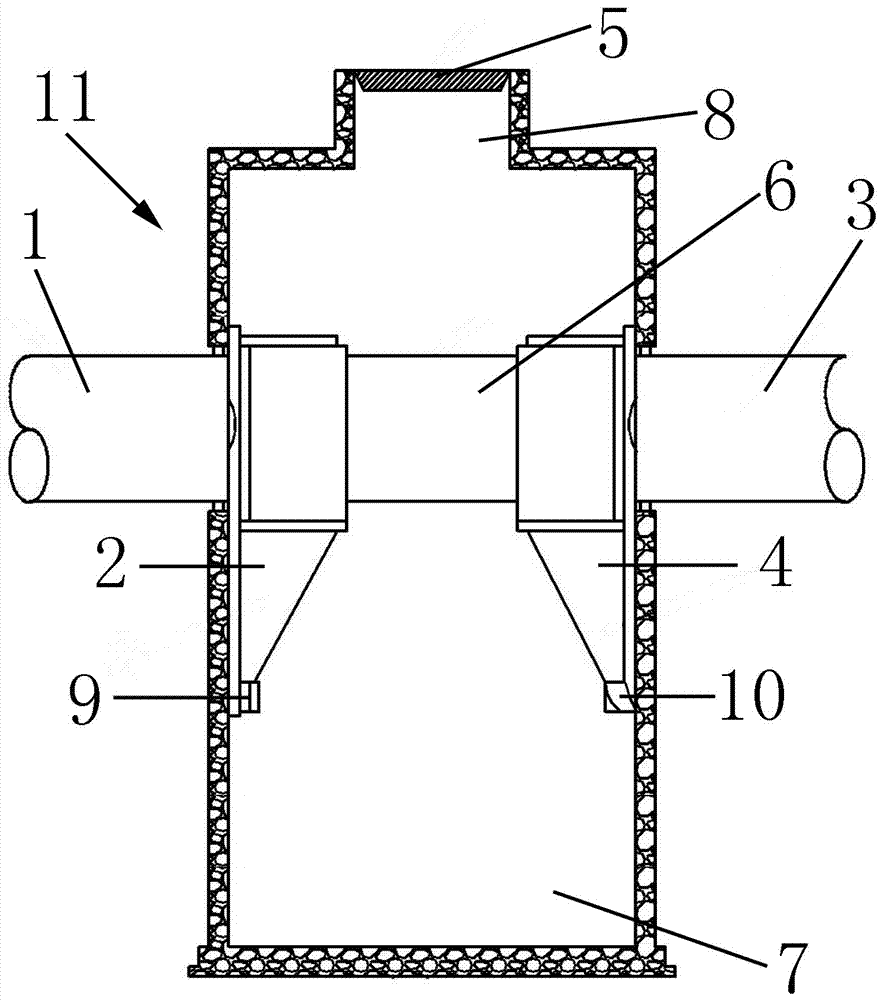
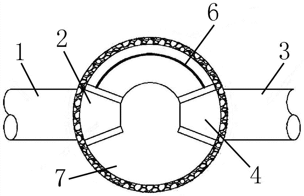
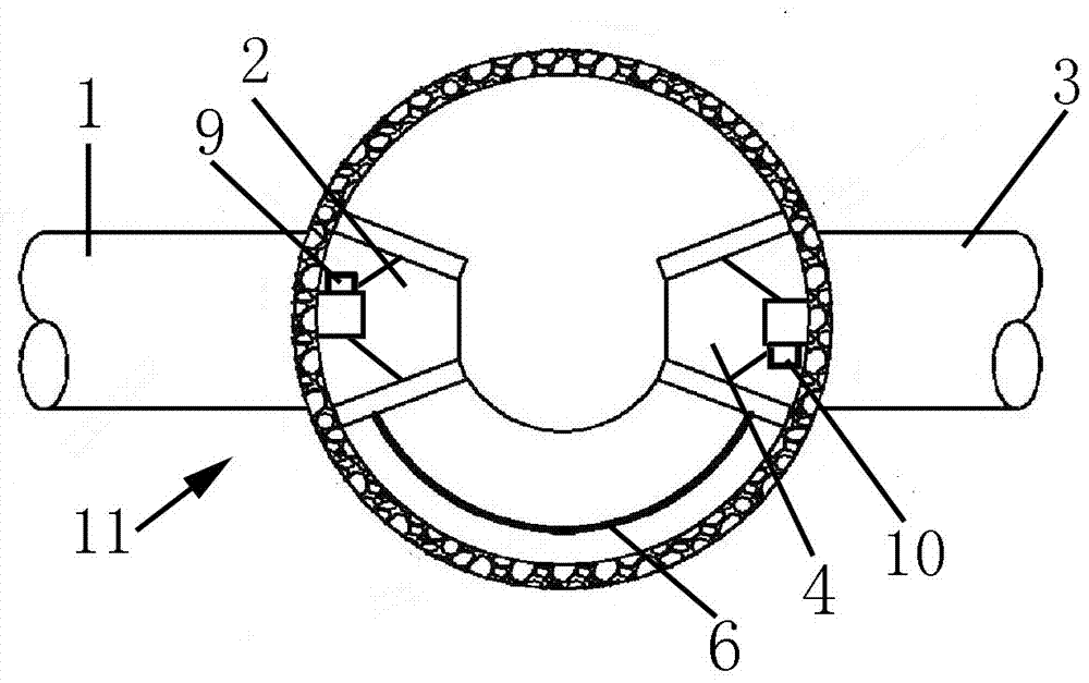
[0024] It consists of the main body of the facility (11), the water inlet pipe (1), the water outlet pipe (6), the guide tube (3), the guide plate (2), the sediment collection area (10), the water outlet collection port (12), the slag discharge The main body of the facility (11) is barrel-shaped as a whole. The main body of the facility (11) is made of cement products, cast iron or modified plastic materials. Water inlet pipes (1) are arranged on both sides of the upper part of the main body of the facility (11). and the water outlet pipe (6), the water inlet pipe (1) and the water outlet pipe (6) are connected with the main body (11) of the facility, the water inlet pipe (1) and the water outlet pipe (6) are made of metal material or modified plastic material, and the facility The water inlet pipe (1) is installed on one side of the main body (11), and the water inlet pipe (1) is inserted into the facility main body (11) at an oblique angle, and the water inlet pipe (1) is con...
Embodiment 2
[0026] A support frame (15) is set in the middle of the main body (11) of the facility, and the support frame (15) is in the shape of a well as a whole, and a guide tube (3) is installed on the support frame (15), and the guide tube (3) is in the shape of a barrel as a whole , the guide tube (3) is made of metal material or modified plastic material, the rainwater is guided into a vortex in the main body (11) of the facility, and the deflector (2) is installed on the lower part of the support frame (15), and the deflector ( 2) The whole is funnel-shaped, the rainwater passes through the deflector (2) to form a vortex, and due to gravity, the sundries in the rainwater fall from the lower opening of the deflector (2) into the sediment collection area (10).
[0027] A slag outlet (8) is installed at the bottom of the main body (11) of the facility, and when the slag outlet (8) is opened, the debris in the sediment collection area (10) is discharged from the slag outlet (8), such a...
Embodiment 3
[0029] The water outlet pipe (6) is installed on the other side of the main body (11) of the facility. The water outlet pipe (6) is a Y-shaped three-way pipe as a whole. One end of the water outlet pipe (6) is an opening, and one end of the water outlet pipe (6) is inserted into the facility. In the main body (11), one end of the water outlet pipe (6) is provided with a water outlet collection port (12), and the water outlet collection port (12) collects rainwater in the main body (11) of the facility, and flows into the water outlet pipe (6), and the water outlet pipe (6) The other end of the outlet pipe (6) is a double port, and the filter layer (4) is installed in the water outlet pipe (6). The filter layer (4) seals one water outlet of the water outlet pipe (6). ), the outlet below the sewage collection area (7) is equipped with a sewage collection area cover (16), and the filtered sludge can be discharged after opening the sewage collection area cover (16), and the filtere...
PUM
 Abstract
Description
Claims
Application Information
 - R&D
- Intellectual Property
- Life Sciences
- Materials
- Tech Scout
- Unparalleled Data Quality
- Higher Quality Content
- 60% Fewer Hallucinations
Browse by: Latest US Patents, China's latest patents, Technical Efficacy Thesaurus, Application Domain, Technology Topic, Popular Technical Reports.
© 2025 PatSnap. All rights reserved.Legal|Privacy policy|Modern Slavery Act Transparency Statement|Sitemap|About US| Contact US: help@patsnap.com


