Rotary hydromechanical meshing characteristic test bench

A technology for fluid machinery and characteristic testing, which is applied in the testing of mechanical components, testing of machine/structural components, testing of machine gears/transmission mechanisms, etc. The meshing principle of conventional fluid machinery and the inability to intuitively display the working principle of the meshing pair have achieved the effect of improving the level of experimental teaching, strong application value, and large degrees of freedom.

Inactive Publication Date: 2018-12-14
CHINA UNIV OF PETROLEUM (EAST CHINA)
View PDF12 Cites 0 Cited by
  • Summary
  • Abstract
  • Description
  • Claims
  • Application Information

AI Technical Summary

Problems solved by technology

However, this test method cannot intuitively show the working principle of the meshing pair, and the research on its meshing characteristics is still at the qualitative research level, and it cannot directly analyze the change law of the meshing gap during the meshing process and the friction and wear of the meshing pair surface. Features to test
The test results obtained by the above method cannot be used to guide the optimization of the mating pair profile
At present, a lot of work has been done on the research of testing and experimental systems, but the experimental platforms proposed in the existing documents (patent numbers: ZL201510007553.4, ZL201510028820.6, ZL201410627748.4, ZL201310524076. Transmission and mechanical failures, suitable for all mechanical learners, failed to involve the deeper principle of rotary fluid mechanical meshing; the test platform mentioned in the existing literature (patent number: ZL201210317303.7, ZL201510486553.7) is used for testing The various properties of the shaft cannot meet the test of the rotary fluid mechanical meshing characteristics of the plane meshing system and the space meshing system, and its versatility is poor and it is not suitable for the requirements of teaching experiments and scientific research experiments

Method used


Image

  • Rotary hydromechanical meshing characteristic test bench
  • Rotary hydromechanical meshing characteristic test bench
  • Rotary hydromechanical meshing characteristic test bench

Examples


Embodiment Construction

[0018] The present invention will be further described below in combination with specific embodiments and accompanying drawings.

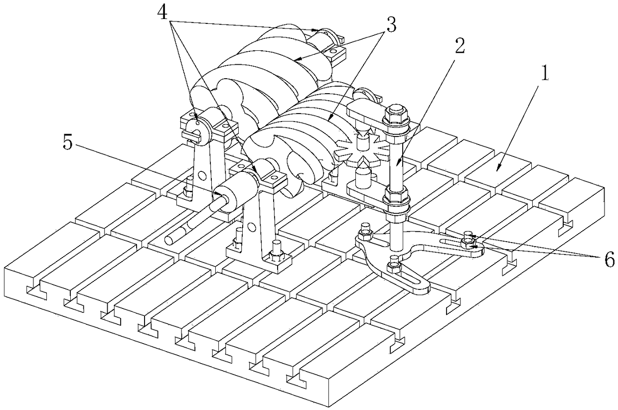
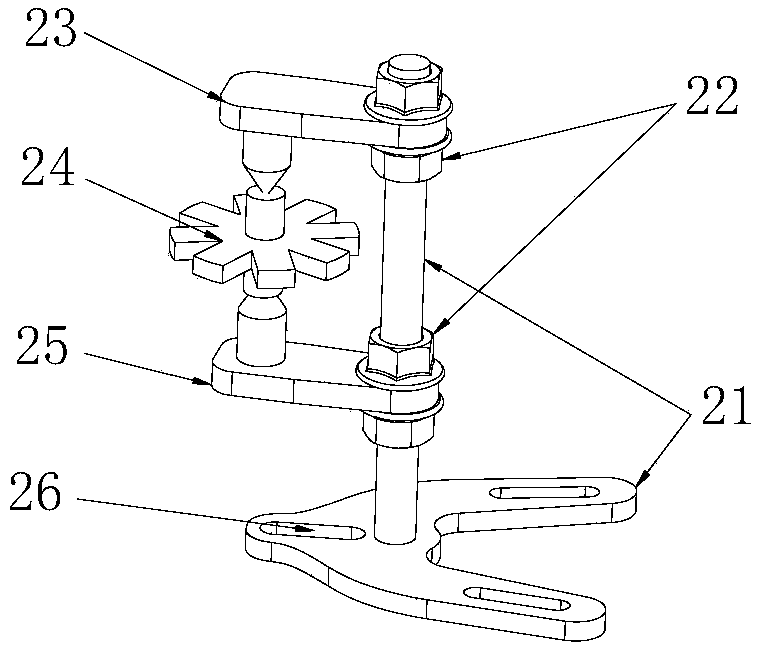
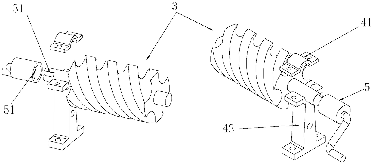
[0019] Such as figure 1 Shown is a test bench for the meshing characteristics of rotary fluid machinery, which mainly includes a staggered T-slot base (1), a vertical axis rotor bracket assembly (2), an meshing rotor (3), an meshing disc (24), a horizontal shaft Rotor support assembly (4), crank handle (5) and fastening assembly (6); vertical axis rotor support assembly (2) and horizontal axis rotor support assembly (4) are connected in a staggered T-shape through fastening assembly (6). On the slot base (1), there are vertically staggered T-shaped slots on the staggered T-slot base (1). Lag bolts can be placed in the T-shaped slots. The lag bolts included in the fastening assembly (6) can be staggered. Free sliding in the T-shaped slot to meet the needs of different installation positions of the bracket components. The lag bolts and nuts can fast...


PUM


Abstract

The invention relates to an experiment table for testing meshing characteristics of rotary fluid machinery, which comprises an interleaved T-slot base (1), a vertical axis rotor bracket assembly (2), a meshing disc (24), meshing rotors (3), horizontal axis rotor bracket assemblies (4), a rocking handle (5) and fastening assemblies (6), wherein the vertical axis rotor bracket assembly (2) and the horizontal axis rotor bracket assemblies (4) are connected on the interleaved T-slot base (1) through the fastening assemblies (6); the meshing rotors (3) are installed on the horizontal axis rotor bracket assemblies (4) and can realize axial fine adjustment; the meshing disc (24) is installed on the vertical axis rotor bracket assembly (2) by relying on an upper tip (23) and a lower tip (25) and can be finely adjusted along the axial direction; and under driving of the rocking handle (5), the meshing disc (24) is matched with the meshing rotors (3) and can realize simulation for the meshing process of a spatial meshing system; and matching of two meshing rotors (3) can realize simulation for the meshing process of a planar meshing system.

Description

technical field [0001] The invention belongs to the field of experimental testing systems, in particular to an experimental platform for testing the engagement characteristics of rotary fluid machinery. Background technique [0002] Rotary fluid machinery is an indispensable and important equipment in petrochemical, refrigeration, air conditioning and air compression industries. The basic working principle of rotary fluid machinery is to rely on the rotary motion of the meshing pair to form a periodically changing working chamber volume to realize the pressurization and delivery of fluid. It has the characteristics of simple structure, high volumetric efficiency and good reliability. According to its working principle, it can be seen that the key to the working performance of rotary fluid machinery is the meshing characteristics of the meshing system of its core working parts. At present, there are many types of rotary fluid machines used in industrial production, and the w...

Claims


Application Information

Patent Timeline
Patent Type & Authority Patents(China)
IPC IPC(8): G01M13/02G01M13/00G09B25/02
CPCG01M13/00G01M13/021G09B25/02
Inventor 王增丽申迎峰武萌石钰王君黄译民张箫笛张晓彤
Owner CHINA UNIV OF PETROLEUM (EAST CHINA)
Why Eureka
Try Eureka