Pump jet propeller model with Helmholtz resonant cavities and design method thereof
A resonant cavity and thruster technology, which is applied in ship design, design optimization/simulation, instruments, etc., can solve problems such as difficult and limited resonant cavity volume, reduce total noise, reduce low-frequency discrete line spectrum noise, and facilitate extended effect
- Summary
- Abstract
- Description
- Claims
- Application Information
AI Technical Summary
Problems solved by technology
Method used
Image
Examples
Embodiment 1
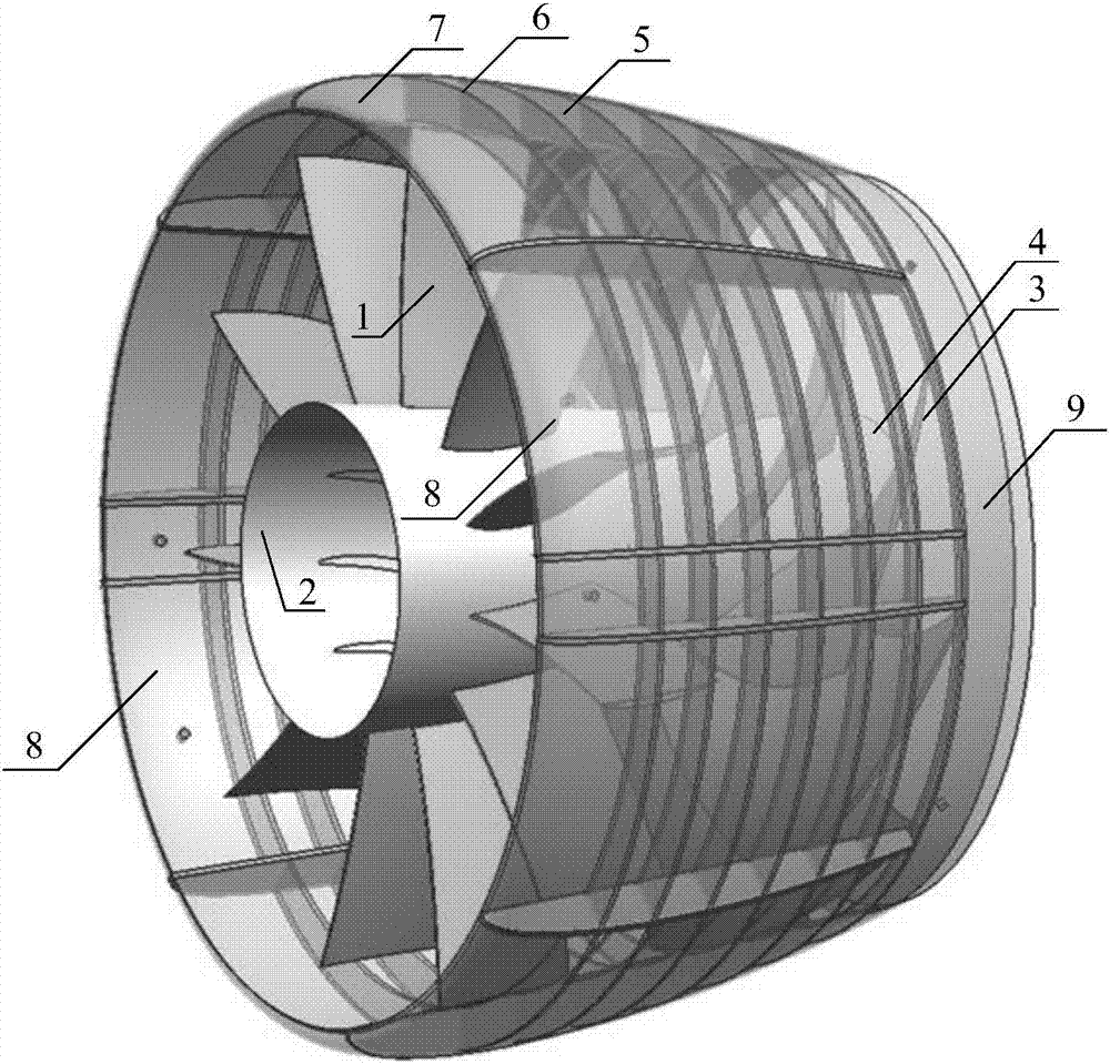
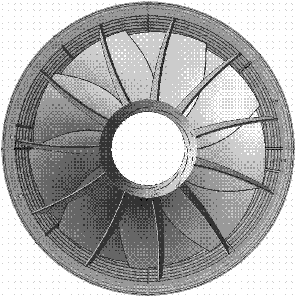
[0045] Such as figure 1 As shown, the pre-stator pump-jet propeller model with the Helmholtz resonance cavity designed by the present invention includes a conduit 5, and a coaxial impeller and a stator are arranged in the conduit 5, the stator is in the front, and the The impeller is placed behind; the impeller includes impeller blades 3 and impeller hub 4, and the impeller blades 3 are circumferentially symmetrically fixed to the impeller hub 4; the stator includes stator blades 1 and stator hub 2, and the stator blades 1 are fixed to the stator The hub 2 and the tip of the stator vane 1 are fixed on the inner wall of the duct 5; the internal rib structure of the duct includes annular ribs 6 and longitudinal ribs 7, the annular ribs 6 are initially arranged at equal intervals in the axial direction, and the longitudinal ribs 7 are arranged unevenly in the circumferential direction; two parallel resonance cavities The Helmholtz resonator 8 is located in front of the first ring...
Embodiment 2
[0057] The flow chart of the design method of the pre-stator pump spray model with the Helmholtz resonance cavity designed by the present invention is as follows Figure 4 as shown,
[0058] In step S1, the hydraulic parameters of the pump jet fluid channel are selected and designed according to the design requirements. When selecting and designing, according to the theory of ship water jet propulsion, the five parameters of pump jet cascade channel head, flow rate, outlet area, specific speed and suction specific speed are determined according to the rapidity requirements.
[0059] Step S2, determine the two-dimensional axial projection geometry of the pump spray front stator, rear impeller, and inner and outer walls of the duct; the two-dimensional axial projection geometry includes the leading edge and trailing edge of the stator blade, the stator hub, the leading edge and the trailing edge of the impeller blade , the axial projection of the impeller hub, the inner and out...
PUM
| Property | Measurement | Unit |
|---|---|---|
| Thickness | aaaaa | aaaaa |
Abstract
Description
Claims
Application Information
 - R&D
- Intellectual Property
- Life Sciences
- Materials
- Tech Scout
- Unparalleled Data Quality
- Higher Quality Content
- 60% Fewer Hallucinations
Browse by: Latest US Patents, China's latest patents, Technical Efficacy Thesaurus, Application Domain, Technology Topic, Popular Technical Reports.
© 2025 PatSnap. All rights reserved.Legal|Privacy policy|Modern Slavery Act Transparency Statement|Sitemap|About US| Contact US: help@patsnap.com


