Electrode formation method for solar battery

A technology for solar cells and electrodes, applied in the field of solar cells, can solve the problems of a large number of masks, complex procedures, disadvantages, etc.

Active Publication Date: 2017-07-14
JIANGSU FOCUS NEW ENERGY TECH
View PDF5 Cites 3 Cited by
  • Summary
  • Abstract
  • Description
  • Claims
  • Application Information

AI Technical Summary

Problems solved by technology

Usually, the electrode patterns or the front electrode contact points are formed by electroplating or screen printing, which requires complex procedures or requires a large number of masks, which is not conducive to reducing costs or simplifying process steps

Method used


Image

  • Electrode formation method for solar battery
  • Electrode formation method for solar battery
  • Electrode formation method for solar battery

Examples


Embodiment Construction

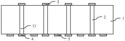
[0027] see Figure 2-19 , solar cell electrode forming method of the present invention, comprises the following steps:

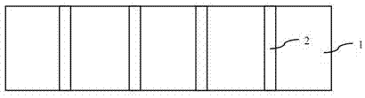
[0028] (1) see figure 2 , providing a battery sheet 1 to be packaged, and forming a conductive through hole 2 connecting the light-receiving surface and the backlight surface of the battery sheet 1;

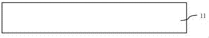
[0029] (2) see image 3 , providing a first silicon slice 11, the shape and size of the first silicon slice 11 are consistent with the battery slice 1;

[0030] (3) see Figure 4 , coating the first photoresist 12 on the upper surface of the first silicon wafer 11, see Figure 5 , and patterned to form a plurality of first openings 13, the plurality of first openings 13 leaking out of the upper surface of the first silicon wafer 11;

[0031] (4) see Figure 6 , using the photoresist 12 as a mask, etching the first silicon wafer 11 by dry etching to form a plurality of first grooves 14;

[0032] (5) see Figure 7 , removing the first photoresist 12;

...


PUM


Abstract

The invention provides a method for producing a solar battery. The method comprises the steps that an upper surface of a silicon wafer with T-shaped via holes is pasted on a back of a battery piece, wherein the via holes correspond to positions at which front electrodes and back electrodes of the solar battery are about to be formed; and coating and annealing of a conductive material are carried out on a backlight surface of the battery piece by taking the silicon wafer as a mask, and the silicon wafer is removed to form a first T-shaped electrode.

Description

technical field [0001] The invention relates to the field of solar cells, in particular to a method for forming solar cell electrodes. Background technique [0002] In the prior art, the electrodes of the solar cell are led to the backlight surface through conductive through holes, so that the area of ​​the light receiving surface can be fully utilized to receive light to the greatest extent. see figure 1 The solar battery sheet 1 leads the front electrode contact point 3 to the front electrode 4 on the backlight surface through the conductive through hole 2, and the back electrode 5 is spaced apart from the front electrode 4 to form an electrode pattern on the back. Usually, the electrode patterns or the contact points of the front electrodes are formed by electroplating or screen printing, which requires complex procedures or a large number of masks, which is not conducive to reducing costs or simplifying process steps. Contents of the invention [0003] Based on solvi...

Claims


Application Information

Patent Timeline
Patent Type & Authority Applications(China)
IPC IPC(8): H01L31/0224H01L31/18
CPCH01L31/022425H01L31/1876Y02E10/50Y02P70/50
Inventor 袁正
Owner JIANGSU FOCUS NEW ENERGY TECH
Why Eureka
Try Eureka