Bone conduction hearing aid device

A hearing aid device, bone conduction technology

Pending Publication Date: 2017-07-14
ZHEJIANG NUROTRON BIOTECH
View PDF3 Cites 1 Cited by
  • Summary
  • Abstract
  • Description
  • Claims
  • Application Information

AI Technical Summary

Problems solved by technology

The software method is limited by its theory and the computing power of the hearing aid can only be optimal in some mathematical or physical sense, and cannot completely remove the feedback signal

Method used


Image

  • Bone conduction hearing aid device
  • Bone conduction hearing aid device
  • Bone conduction hearing aid device

Examples


Embodiment 1

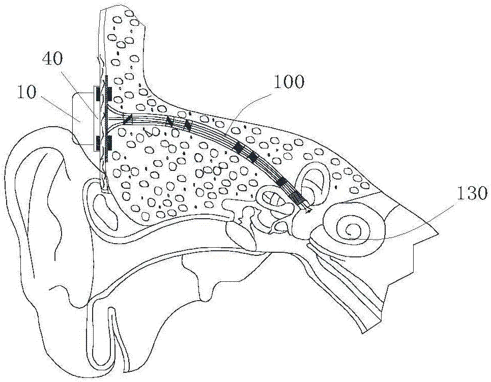
[0024] Embodiment 1: refer to Figure 1-6 . A bone conduction hearing aid device, comprising an extracorporeal speech processor 10, the extracorporeal speech processor 10 includes a housing 11, a metal plate 40, and an electromagnetic vibrator 25 placed in the housing 11, several microphones, integrated with digital The circuit board 12 of the signal processing chip DSP 80, the digital signal processing chip DSP 80 includes but not limited to CPU, processor, microprocessor, controller, microcontroller etc., the digital signal processing chip DSP 80 is set through program, can according to The external voice signal input by the microphone produces the voice output signal that drives the electromagnetic vibrator 25, and the external voice processor 10 can use a plurality of digital signal processing chips DSP 80 to complete different functions; External communication or a wireless or wired communication circuit programmed by an external device; the microphone includes a receive...

Embodiment 2

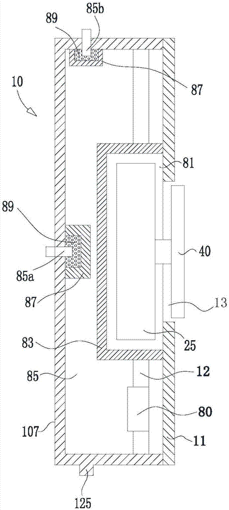
[0025] Embodiment 2: refer to figure 2 , image 3. The microphone includes a first microphone 85a and a second microphone 85b. The left side wall of the housing 11 is provided with the first microphone 85a, and the wall at the top of the housing is provided with the second microphone 85b. The first microphone 85a, the second microphone 85b are electrically connected to the circuit board 12 respectively. The left side wall and the top wall of the housing 11 are respectively provided with a microphone packaging compartment 87, and the first microphone 85a and the second microphone 85b are respectively placed in the corresponding microphone packaging compartments 87. A resonant sound-absorbing pad 89 is provided between the first microphone 85a, the second microphone 85b and the microphone packaging compartment 87 at the corresponding positions. Both the microphone package compartment 87 and the vibrator package compartment 83 can prevent, attenuate, block, and reduce sound t...

Embodiment 3

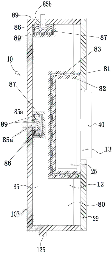
[0026] Embodiment 3: refer to image 3 . On the basis of Embodiment 2, each microphone packaging partition bin 87 is respectively provided with a microphone packaging inner partition bin 86, and the first microphone 85a and the second microphone 85b are respectively placed in the microphone packaging inner partition bin 86 at the corresponding position. , and the resonant sound-absorbing pads 89 are provided between the microphone package compartment 87 and the microphone package inner compartment 86, and between the first microphone 85a, the second microphone 85b and the microphone package inner compartment 86 at corresponding positions. The purpose of this structure is to set up a multi-layer sound insulation structure, so as to enhance the effect of partition and sound attenuation.

[0027] The vibrator package partition compartment 83 is provided with a vibrator package inner partition compartment 82 , the electromagnetic vibrator 25 is placed in the vibrator package inne...


PUM


Abstract

The invention relates to a bone conduction hearing aid device, comprising an in-vitro voice processor which comprises a shell, a metal disk, an electromagnetic vibrator placed in the shell, a microphone and a circuit board, wherein a digital signal processor DSP is integrated and mounted on the circuit board. A vibrator packaging and separating cabin is arranged in the shell. A port is arranged on the right side wall of the shell. The port is communicated with the vibrator packaging and separating cabin. An output end part of the electromagnetic vibrator stretches out of the port and is connected with the metal disk. At least one microphone is arranged on the wall of the shell. The electromagnetic vibrator is arranged in the vibrator packaging and separating cabin. The port is communicated with the vibrator packaging and separating cabin. The output end part of the electromagnetic vibrator stretches out of the port and is connected with the center of the metal disk. According to the device, the electromagnetic vibrator is placed in the vibrator packaging and separating cabin. The sound propagated from the electromagnetic vibrator to the microphone is reduced and attenuated, so the sound propagated form the electromagnetic vibrator to the microphone is reduced or attenuated, and the howling of the bone conduction hearing aid device is greatly weakened.

Description

technical field [0001] The invention relates to a hearing aid, in particular to a bone conduction hearing aid. Background technique [0002] A bone anchor hearing aid is a hearing aid based on the theory of bone conduction. It is divided into an external speech processor part and an implant part implanted in the patient's head. The bone anchor hearing aid uses the human skull as a channel for sound transmission into the inner ear. For conduction For patients with permanent deafness, the bone-anchor hearing aid bypasses the patient's outer ear and middle ear, and transmits the sound directly to the patient's normal cochlea through a metal implant; One layer goes to the normal side. Most bone-anchored hearing aids require a titanium rod or plate to be surgically implanted into the skull with a small joint that exposes the patient's skin; the voice processor of the bone-anchored hearing aid is mounted on this joint , and transmit the sound vibration to the implant through the ...

Claims


Application Information

Patent Timeline
Patent Type & Authority Applications(China)
IPC IPC(8): H04R25/00
CPCH04R25/50H04R2225/43
Inventor 牛晓辉芮立扬李祖河屠文河
Owner ZHEJIANG NUROTRON BIOTECH
Why Eureka
Try Eureka