
Low-k material laser removal process and its equipment

A 1.low-k, laser technology, used in laser welding equipment, metal processing equipment, welding equipment, etc., can solve problems such as poor effect, achieve optimized processing effect, good processing cutting track shape, and high processing efficiency Effect

Active Publication Date: 2019-06-18
苏州镭明激光科技有限公司
View PDF5 Cites 0 Cited by
  • Summary
  • Abstract
  • Description
  • Claims
  • Application Information

AI Technical Summary

Problems solved by technology

The disadvantage of this scheme is that the processing focus is Gaussian light
The distribution of Gaussian light causes the processed cutting line to be V-shaped, and the effect is not good

Method used

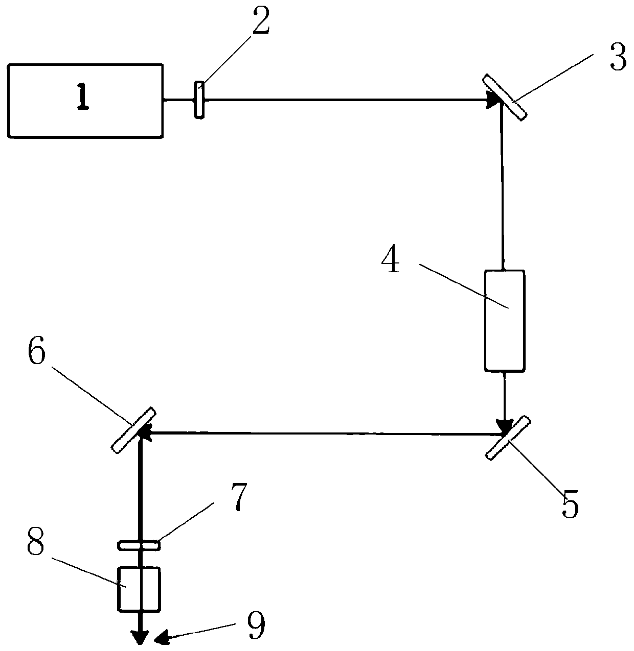

Image

  • Low-k material laser removal process and its equipment
  • Low-k material laser removal process and its equipment

Examples


Embodiment 1

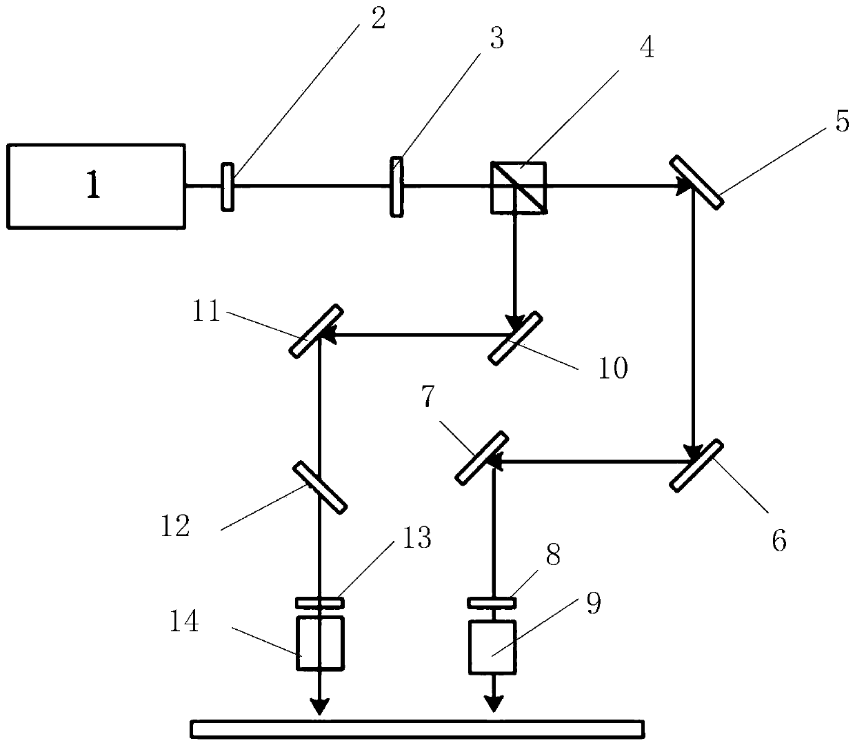
[0041] A 355nm ultraviolet laser with an output power of 12W and a pulse width of 90ns is used. The laser beam is transmitted to the half-wave plate 3 through the opened shutter 2, and then becomes linearly polarized light with adjustable polarization direction. The linearly polarized light is divided into two beams of laser light after passing through the polarization beam splitter 4, and the P light can directly pass through the polarization beam splitter. The mirror 4 continues to propagate, and the S light is reflected by the polarization beam splitter 4 and then enters the first reflector 10 to form two paths of independently propagating laser light.

[0042]The middle half-wave plate 3 is driven by a servo motor and can rotate 360 ​​degrees. During the rotation, the power of the transmitted P light and the reflected S light changes. The P light separated from the laser beam passes through the reflector 5 and continues to propagate to the reflector 6 and the reflector 7, ...

Embodiment 2

[0045] The laser used has a wavelength of 355nm and a variable pulse width of 20-120ns. The laser can also be an ultrashort pulse laser with a wavelength range of 355nm-1070nm.

[0046] During the implementation period, the half-wave plate is driven by a servo motor, installed in a circular mechanism, driven by the motor to rotate, and the rotation accuracy is not less than 0.5 degrees. In this way, as the angle changes, the output power of the polarizing beam splitter 4 will continue to change, where the polarizing beam splitter 4 can be a polarizing cube or a film polarizer.

[0047] Furthermore, the first focusing lens 9 and the second focusing lens 14 used can be combined into one, further improving the processing efficiency. At the same time, the polarization beam splitter 4 can also be driven by a ceramic motor to meet the high-precision 360-degree rotation. With the change of the angle of the beam splitter, the distance between the scribing spot relative to the platform...


PUM

PropertyMeasurementUnit
wavelengthaaaaaaaaaa

Abstract

The invention relates to a low-k material laser removing technology and a device thereof. Dual-beam laser is adopted to be focused, then, machining is carried out, one beam of laser is shaped to form plane top pumping light, smoothing is carried out on the middle of the material, the other beam of laser is divided into two independent light points, the two sides of a cutting way are trimmed, and therefore the one beam of laser can be divided into two beams, shaping and focusing are carried out, one beam is used for machining the middle area, the middle area is removed, the other beam is used for machining two sides, it is ensured that the morphology of the machined bottom is flatly distributed, and the machining effect and the product yield are improved.

Description

technical field [0001] The invention relates to a micromachining method and its equipment, in particular to a Low-k material laser removal process and its equipment. Background technique [0002] In the field of integrated circuits and semiconductors, the integration of high-speed electronic components is getting higher and higher. Inside integrated circuits, due to the existence of ILD (Inter Layer Dielectrics, interlayer dielectrics), there is inevitably distributed capacitance between wires, or called It is the parasitic capacitance. Distributed capacitance not only affects the speed of the chip, but also poses a serious threat to the reliability of the work. From the capacitor capacity calculation formula, we can see that in the case of the same structure, reducing the k value of the dielectric can reduce the capacity of the capacitor. Therefore, using a low-k dielectric as the ILD can effectively reduce the distributed capacitance between interconnect lines, thereby i...

Claims


Application Information

Patent Timeline
Patent Type & Authority Patents(China)
IPC IPC(8): B23K26/38B23K26/36B23K26/40B23K26/046B23K26/064
CPCB23K26/046B23K26/064B23K26/0643B23K26/36B23K26/38B23K26/40B23K2101/40
Inventor 施心星韩伟邵西河
Owner 苏州镭明激光科技有限公司
Learn More