Greenhouse roller shutter control system

A control system and rolling shutter technology, applied in general control systems, control/regulation systems, program control, etc., can solve the problems of large volume and high power consumption, and achieve the effects of good stability, low power consumption and fast installation speed.

Inactive Publication Date: 2017-07-18
SHANDONG YANTAI AGRI SCI & TECH INST
View PDF9 Cites 0 Cited by
  • Summary
  • Abstract
  • Description
  • Claims
  • Application Information

AI Technical Summary

Problems solved by technology

[0003] The technical problem to be solved by the present invention is to provide a greenhouse roller blind control system to solve the problems of large volume and high power consumption in the existing greenhouse roller blind control mode

Method used


Image

  • Greenhouse roller shutter control system
  • Greenhouse roller shutter control system
  • Greenhouse roller shutter control system

Examples


specific Embodiment

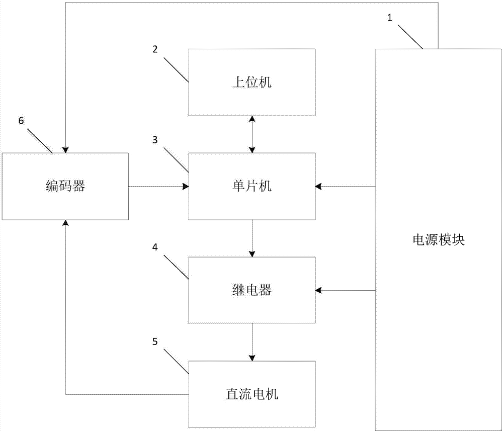
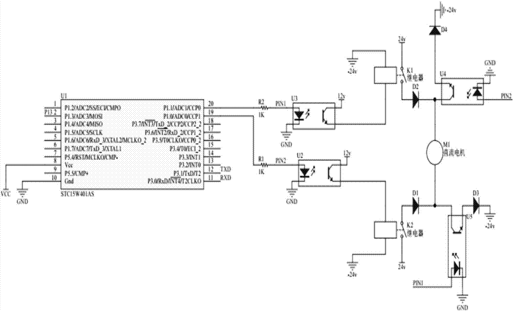
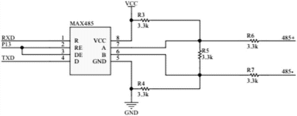
[0029] see figure 2 , image 3 The specific embodiment of the present invention shown: the single-chip microcomputer 3 includes a single-chip microcomputer U1, and the relay 4 includes a relay K1 and a relay K2. Wherein the 20th pin and the 19th pin of the single-chip microcomputer U1 are respectively connected to the relay K1 and the relay K2, and the relay K1 and the relay K2 are respectively connected to the DC motor 5 (that is, the attached figure 2 On the positive and negative power supply lines of the DC motor M1). The single-chip microcomputer U1 is connected to the upper computer 2 through the communication module. The model of microcontroller U1 is STC15W408. like image 3 As shown, the communication module is a communication interface chip modeled as MAX485, and the first pin of the communication module is connected to the eleventh pin of the single-chip microcomputer U1. The 2nd pin and the 3rd pin of the communication module are connected to the 2nd pin of t...


PUM


Abstract

The invention discloses a greenhouse roller shutter control system which comprises a power supply module, an upper computer, a single-chip microcomputer, a relay, an encoder and a DC motor for driving the greenhouse roller shutter. The output end of the power supply module is connected with the relay and the single-chip microcomputer, thereby supplying electric power to the relay and the single-chip microcomputer. The output end of the power supply module is connected with the DC motor through the relay, thereby supplying electric power to the DC motor through the relay. The encoder is mounted on the motor shaft of the DC motor for detecting a real-time operation state of the DC motor. The signal output end of the encoder is connected with the single-chip microcomputer for transmitting the operation state to the single-chip microcomputer. The single-chip microcomputer is connected with the upper computer and the relay for receiving a control signal which is transmitted from the upper computer for controlling the operation state, and controls the operation state of the DC motor through the relay. The greenhouse roller shutter control system has advantages of high stability, low cost, low power consumption, low heating amount, no requirement for complicated programming, high field mounting speed, high effect and high suitability for actual production.

Description

technical field [0001] The invention relates to the field of motor control, in particular to a greenhouse roller blind control system. Background technique [0002] The ventilation operation of the agricultural greenhouse is realized by pulling the canopy film in the forward and reverse directions, and it is usually controlled by manually operating the forward and reverse directions of the DC motor. With the development of the intelligent Internet of Things in the agricultural field, refined automatic control has become a new requirement for greenhouses, which makes the original manual control of the motor into the use of remote communication to drive the operation of the motor. At present, PLC or 51 / 52 single-chip microcomputer is usually used to control the operation of the motor in this field. Although these existing control methods can realize remote control of greenhouse roller blinds, they are large in size, high in cost, high in power consumption, and low in durabili...

Claims


Application Information

Patent Timeline
Patent Type & Authority Applications(China)
IPC IPC(8): G05B19/042A01G9/22
CPCA01G9/227G05B19/042Y02A40/25
Inventor 杨剑超姜学玲李廷菊孙晓徐维华孙妮娜张瑞清汤国民王新语王培松郑秋玲唐美玲
Owner SHANDONG YANTAI AGRI SCI & TECH INST
Why Eureka
Try Eureka