A Transverse Flux Magnetic Field Modulation Linear Motor

A linear motor and magnetic field modulation technology, which is applied in the direction of electromechanical devices, electrical components, electric components, etc., can solve the problems of reduced fault-tolerant performance, and achieve the effects of improved space utilization, improved fault-tolerant performance, and high reliability

Active Publication Date: 2019-05-14
湖南天友精密技术有限公司
View PDF4 Cites 0 Cited by
  • Summary
  • Abstract
  • Description
  • Claims
  • Application Information

AI Technical Summary

Problems solved by technology

The linear motor based on magnetic field modulation has been developed rapidly due to its advantages of compact structure, high power density and high efficiency, but there is coupling between the phases of the magnetic field, and the fault tolerance performance is reduced. Therefore, a transverse flux magnetic field modulation is proposed. On the one hand, the armature winding and the stator slots are perpendicular to each other in space, which realizes the decoupling of the electric load and the magnetic load, and can increase the output by increasing the rate of change of magnetic energy within a certain range; on the other hand, each phase They are decoupled from each other, which is convenient for independent control, and is easy to design into a multi-phase structure. In multi-phase operation, even if one phase is missing, it can work normally. The fault tolerance performance is good, and the reliability of the motor is improved.

Method used


Image

  • A Transverse Flux Magnetic Field Modulation Linear Motor
  • A Transverse Flux Magnetic Field Modulation Linear Motor
  • A Transverse Flux Magnetic Field Modulation Linear Motor

Examples


Embodiment Construction

[0021] The principles and features of the present invention will be described below with reference to the accompanying drawings. The examples are only used to explain the present invention, but not to limit the scope of the present invention.

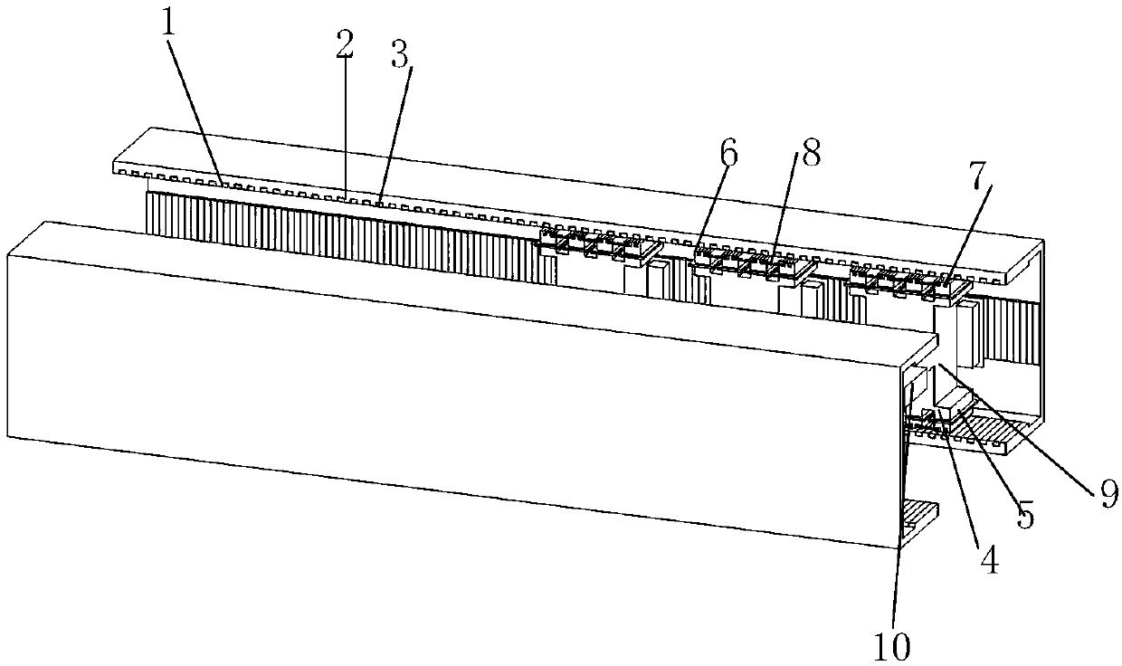
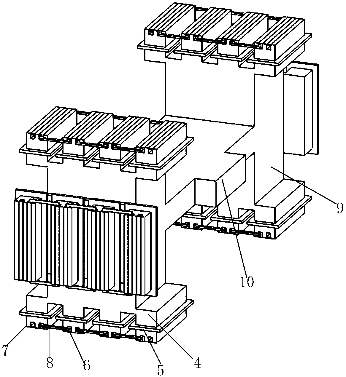
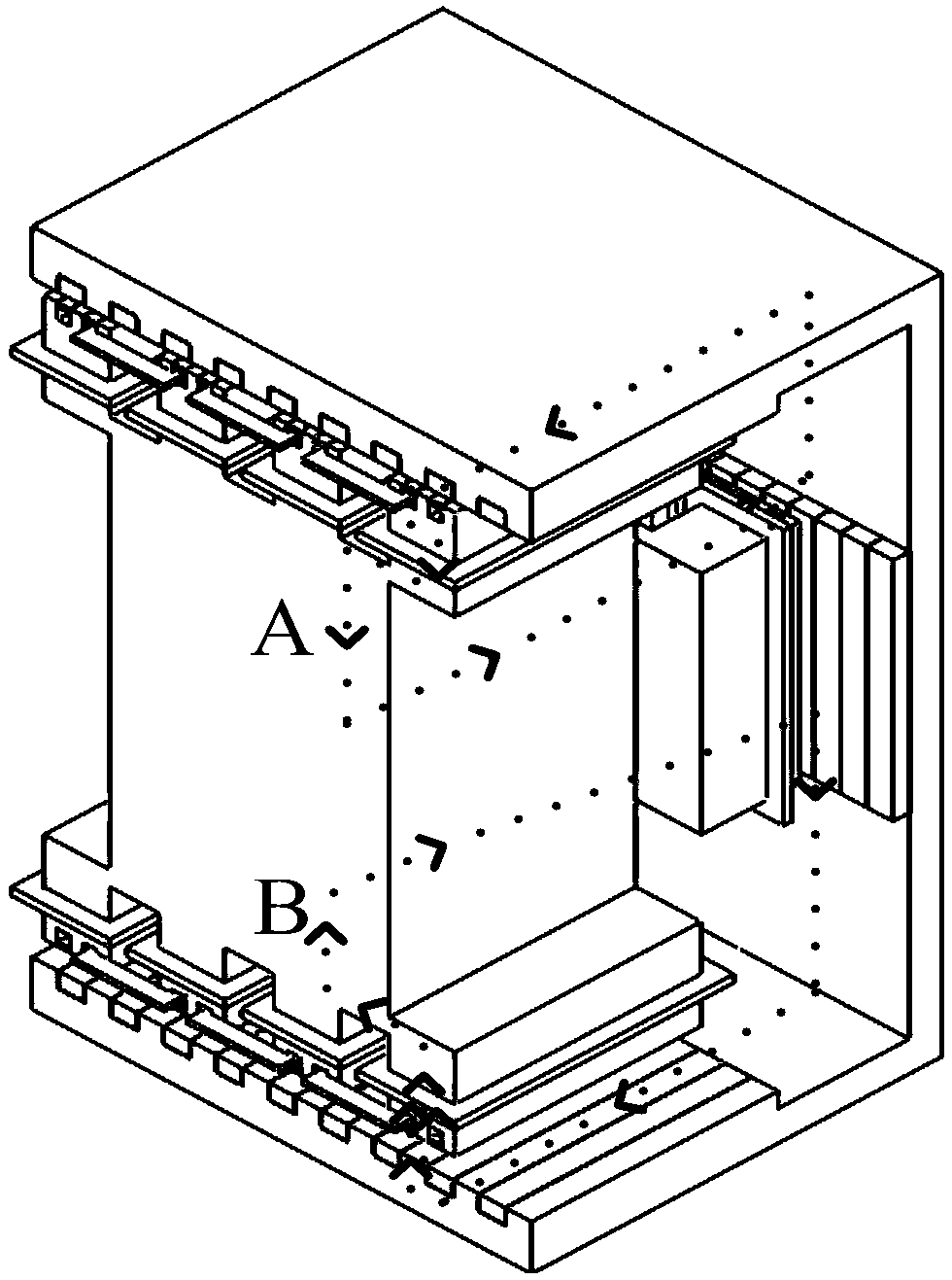
[0022] Please refer to figure 1 As shown, it is a schematic structural diagram of the transverse magnetic flux magnetic field modulation type linear motor of the present invention. The transverse magnetic flux magnetic field modulation type linear motor includes: a primary and a secondary; the present invention combines magnetic field modulation on the basis of transverse magnetic flux In the proposed field-modulated motor, the two secondary stages are formed by stacking silicon steel sheets in a "C" shape and are arranged in a mirror image, so that there is three-sided air between the primary and the secondary. There are no cumbersome armature windings on the inner three sides of the "C" shape, but multiple secondary slots 1 and multip...


PUM


Abstract

The invention discloses a transverse flux magnetic field modulation type linear motor. The linear motor comprises primary bodies and secondary bodies. The two secondary bodies are in a C-shaped, mirror image arrangement, and three air gaps are arranged among the primary body and the secondary bodies. The inner sides of the secondary bodies are provided with a plurality of secondary grooves and a plurality of secondary teeth at equal intervals, and secondary permanent magnets are disposed in the secondary grooves. Each of the primary bodies comprises two same primary iron cores and a connecting beam used for connecting the two primary iron cores. The upper surfaces and the lower surfaces of the primary iron cores and the surfaces of the primary iron cores back to the connecting beams are provided with salient pole teeth, which are arranged at equal intervals, and are the same. The salient pole teeth are provided with salient armature windings in a coiled manner, and are provided with virtual teeth, and virtual grooves are arranged among adjacent virtual teeth, and in addition, virtual groove permanent magnets are disposed in the virtual grooves. Virtual groove armature windings are disposed in the virtual grooves. The three phases of the primary bodies are provided with three phases of armature windings. The armature winding of the same primary body is used to form one phase, and the armature windings of the three primary bodies are used to form three phases, and a difference among currents flowing through the three phases is 120degrees. The transverse flux magnetic field modulation type linear motor adopts modularization design, and has advantages of simple structure, and ability of improving fault-tolerant performance.

Description

technical field [0001] The invention relates to a magnetic field modulation type linear motor, in particular to a transverse magnetic flux magnetic field modulation type linear motor. Background technique [0002] The linear direct drive motion system eliminates the need for complex mechanical conversion devices. The system has a simple structure, reliable operation, fast response speed and high control accuracy. It has a wide range of needs and applications in aviation, aerospace and other military and civil industries. As the core component of the linear direct drive motion system, the linear motor has always been the preferred electric drive solution for the linear direct drive motion system, and it is also an effective means to solve the above problems. The linear motor based on magnetic field modulation has been developed rapidly due to its advantages of compact structure, high power density and high efficiency. On the one hand, the armature winding and the stator slot...

Claims


Application Information

Patent Timeline
Patent Type & Authority Patents(China)
IPC IPC(8): H02K41/03
CPCH02K41/031
Inventor 赵玫王曼曼徐明铭韩辅君邓冠龙邹海林王刚杨洪勇侯典立张淑宁张平刘飞牟博文
Owner 湖南天友精密技术有限公司
Why Eureka
Try Eureka