
VCO circuit with low power and high performance

A high-performance, low-power technology, applied in the field of circuits, can solve the problems of VCO output frequency variation, small VCO frequency adjustable range, unacceptable temperature characteristics, etc., to achieve the effect of improving linearity and stability

Active Publication Date: 2017-07-18
JIANGSU COLLEGE OF INFORMATION TECH
View PDF6 Cites 6 Cited by
  • Summary
  • Abstract
  • Description
  • Claims
  • Application Information

AI Technical Summary

Problems solved by technology

This kind of voltage-controlled oscillator uses a transmission gate as a voltage-controlled resistor, but since the on-resistance of the MOS tube depends on the width-to-length ratio of the tube, and the tube’s width-to-length ratio is limited by factors such as processing, the frequency of the VCO with this structure can be The adjustment range is small, which cannot be satisfied in many applications
[0011] In addition, in the prior art, the VCO output frequency will change with the change of temperature
To give an example, at room temperature, when the output frequency is 20MHz, the frequency variation of the traditional VCO is about 6.57MHz, while the variation of the existing VCO is relatively small, but there is still 0.9MHz, according to the percentage The calculation also reaches 4.5%, such temperature characteristics are unacceptable in many VCO applications

Method used


Image

  • VCO circuit with low power and high performance
  • VCO circuit with low power and high performance
  • VCO circuit with low power and high performance

Examples


Embodiment Construction

[0033] The specific embodiments of the present invention will be further described below in conjunction with the accompanying drawings.

[0034] The technical scheme adopted in the present invention is:

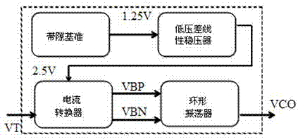
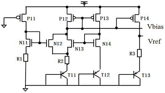
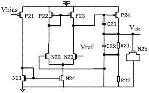
[0035] like Figure 1 to Figure 8As shown, a low-power high-performance VCO circuit includes a bandgap reference circuit, a low-dropout linear voltage regulator circuit LDO, a current converter circuit and a ring oscillator circuit, and the bandgap reference circuit, low-dropout linear voltage regulator circuit , the current converter circuit and the ring oscillator circuit are connected sequentially from left to right, the bandgap reference circuit is used to provide a reference voltage that does not vary with temperature and power supply voltage, and the low dropout linear regulator circuit LDO is used to use the bandgap The voltage generated by the reference is doubled and the output voltage remains constant. The current converter circuit includes a three-layer conversion...


PUM


Abstract

The invention discloses a VCO circuit with low power and high performance. The VCO circuit comprises a band-gap reference circuit, a low dropout voltage linear voltage-stabilizing circuit, a current converter circuit, and an annular oscillator circuit which are orderly connected from left to right; the band-gap reference circuit is used for providing a reference voltage which cannot change along with the temperature and a power voltage; the low dropout voltage linear voltage-stabilizing LDO is used for doubling the band-gap reference produced voltage and maintaining the output voltage unchanged; the current converter circuit comprises three layers of conversion devices; the annular oscillator circuit is composed of five stages of oscillators in parallel; the VCO circuit disclosed by the invention is high in output frequency, small in change along the process and large in frequency adjustable range under low voltage; an output frequency of a voltage-controlled oscillator is small in change along the temperature, the chip cost is low, the circuit structure is simple, and the power consumption is low.

Description

technical field [0001] The invention relates to the field of circuits, in particular to a low-power and high-performance VCO circuit. Background technique [0002] Oscillators are electronic components used to generate repetitive signals such as sine waves and square waves. They are widely used in various fields such as communications, electronics, aerospace, and medicine. Provide the oscillation frequency that changes with the voltage and become an important part of the radio frequency circuit, also known as frequency modulation, which is used to generate frequency modulation signals. It is widely used in modern communication technology, Bluetooth technology, etc. In the field of electronic communication technology, VCO and current Sources and op amps are equally important. [0003] The initial VCOs were all assembled with discrete components. As the communication field continuously puts forward requirements for terminal products such as lightness, thinness, shortness, and...

Claims


Application Information

Patent Timeline
Patent Type & Authority Applications(China)
IPC IPC(8): H03L7/099
CPCH03L7/0995
Inventor 居水荣石径王天赦
Owner JIANGSU COLLEGE OF INFORMATION TECH
Learn More