Friction wedge type automatic clamp for cylindrical grinding and application method thereof

A friction wedge, automatic technology, applied in the direction of grinding workpiece support, etc., can solve the problems of low degree of automation, eccentric rotation of the workpiece, affecting machining accuracy, etc., to achieve automatic clamping, ensure grinding accuracy, and improve clamping accuracy Effect

Active Publication Date: 2017-07-21
QUZHOU COLLEGE OF TECH
View PDF8 Cites 9 Cited by
  • Summary
  • Abstract
  • Description
  • Claims
  • Application Information

AI Technical Summary

Problems solved by technology

The first type requires manual adjustment of the chuck jaws to clamp the workpiece separately during clamping. The degree of automation is not high, and when the clamping force of the jaws is inconsistent, it is easy to clamp the workpiece, causing the rotation axis of the workpiece to not coincide with the centerline of the headstock spindle. It is bound to cause eccentric rotation of the workpiece during grinding, thus affecting the machining accuracy
The second method adopts the electromechanical hydraulic power method. While the automation degree of the machine tool fixture is improved, its cost is also increased accordingly.

Method used


Image

  • Friction wedge type automatic clamp for cylindrical grinding and application method thereof
  • Friction wedge type automatic clamp for cylindrical grinding and application method thereof
  • Friction wedge type automatic clamp for cylindrical grinding and application method thereof

Examples


Embodiment Construction

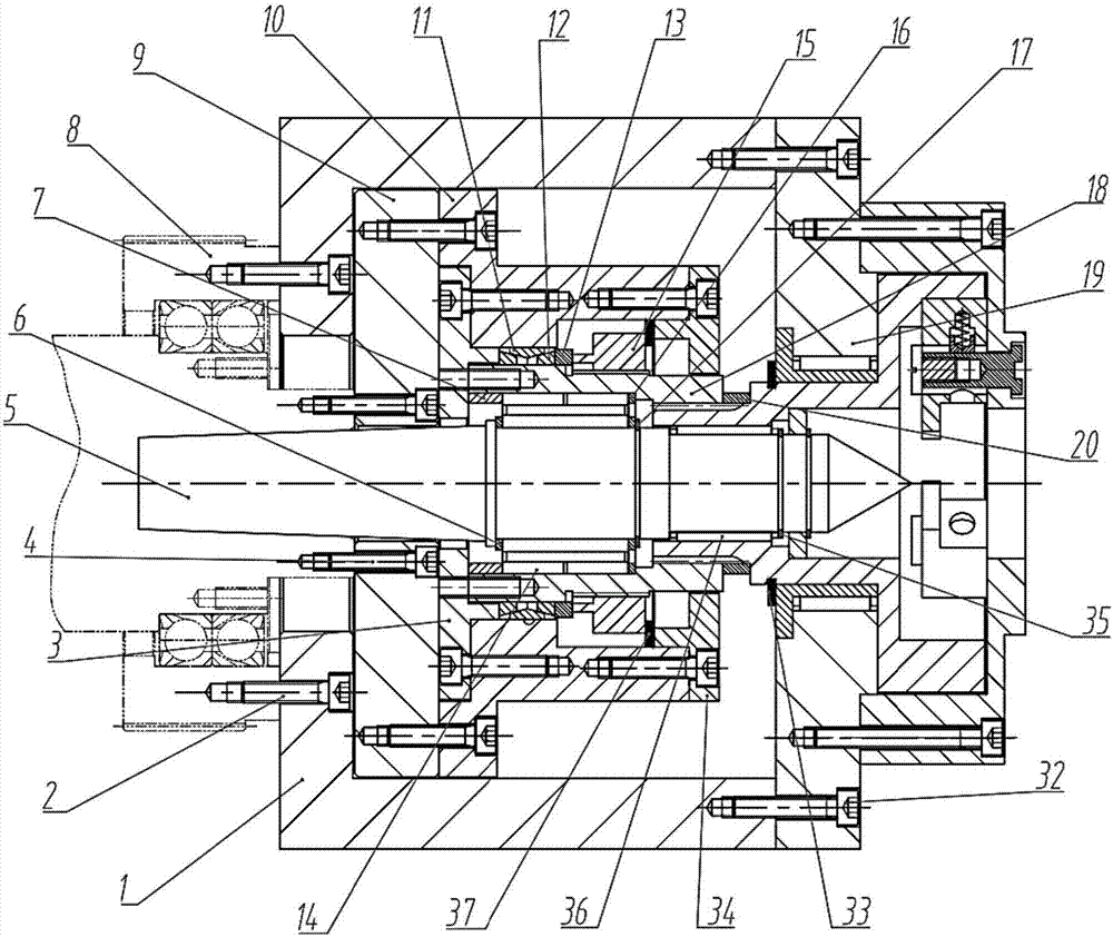
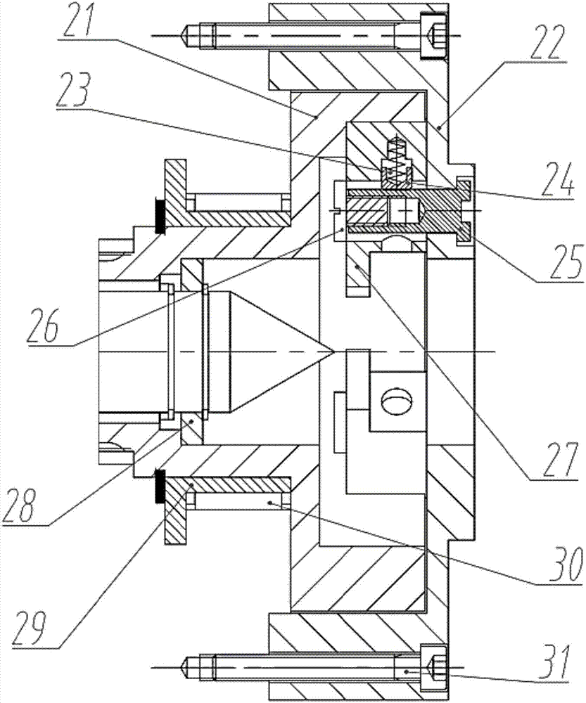
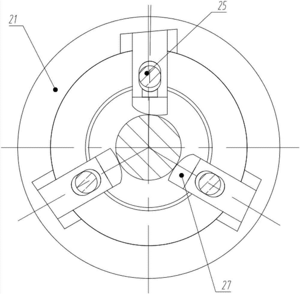
[0019] Such as figure 1 , 2 As shown, the friction wedge type external grinding automatic fixture includes connecting flange 1, screw M6X252, left end cover 3, screw M5X254, head frame top 5, spacer 6, bearing positioning sleeve 7, machine tool head frame pulley 8, positioning Flange 9, intermediate sleeve 10, outer cone spring 11, inner cone spring 12, spring positioning piece 13, complete needle roller bearing 14, hex nut 15, bearing positioning ring 16, stop ring 17, spline inner sleeve 18 , support ring 19, positioning sleeve 20, wedge ring 21, dial ring 22, return spring 23, spring sleeve 24, dial pin 25, dial nut 26, wedge 27, spacer 28, support ring positioning sleeve 29, Needle bearing 30, screw M6X5031, screw M6X3032, sleeve stop ring 33, right end cover 34, top stop ring 35, needle bearing 36 and spacer 37;

[0020] The connecting flange 1 and the positioning flange 9 are fastened to the gear rotor and stator of the pulley 8 of the machine head frame through screws...


PUM


Abstract

The invention discloses a friction wedge type automatic clamp for cylindrical grinding and an application method thereof. The friction wedge type automatic clamp for cylindrical grinding comprises a connecting flange, a left end cover, a head rack tip, a positioning flange, an intermediate sleeve, a hexagonal nut, a spline inner sleeve, a supporting ring, a wedge ring, a shifting ring, wedges, a supporting ring positioning sleeve, a needle bearing and a right end cover, wherein the connecting flange is mounted onto a gear of a head rack through a screw; the connecting flange, the supporting ring and the shifting ring are sequentially fixed through the screws; the shifting ring is connected with three wedges through three uniformly-distributed shifting pins; the three wedges are correspondingly embedded into three bevel grooves of the wedge ring; the positioning flange is fixed to a machine body of the head rack and is fixedly connected with the intermediate sleeve; the spline inner sleeve is connected with the wedge ring; a pre-tensioned inner conical spring and a pre-tensioned outer conical spring are mounted between the intermediate sleeve and the spline inner sleeve. According to the friction wedge type automatic clamp for the cylindrical grinding, an automatic wedge clamping manner is used for replacing an existing general manual chuck and a hydraulic driving chuck, so that the structure is simplified, and meanwhile, the automatic clamping function is achieved; in addition, the grinding precision is ensured.

Description

technical field [0001] The invention relates to a wedge type cylindrical grinding machine fixture, in particular to a high-precision quick-change cylindrical grinding automatic fixture that can automatically clamp and loosen workpieces. Background technique [0002] As a high-precision processing technology, grinding has a very important influence on the processing quality and assembly accuracy of parts. In actual processing, the amount of labor consumed by cylindrical grinding and the possible accuracy have a lot to do with the clamping method and the centering accuracy of the fixture. At present, in the structure of the headstock of the cylindrical grinding machine, the clamping positioning and rotary motion of the workpiece mainly include: 1. Use the top of the headstock and the tailstock to tighten the workpiece, and then manually adjust the three jaws on the chuck to clamp the workpiece and drive The workpiece is rotated; 2. The top between the headstock and the tailst...

Claims


Application Information

Patent Timeline
Patent Type & Authority Applications(China)
IPC IPC(8): B24B41/06
CPCB24B41/062B24B41/067
Inventor 林钰珍陈澜徐文俊巫少龙顾怡红毛方
Owner QUZHOU COLLEGE OF TECH
Why Eureka
Try Eureka