
Box-type waste heat recovering device of sintered ores

A waste heat recovery device and sinter technology, which is applied in the field of sinter waste heat recovery, can solve the problems of entrained sinter dust environmental pollution, the quality reduction of flue gas heat energy, and low heat energy recovery efficiency, and achieve good air tightness and waste heat recovery. The effect of high quality and low system resistance

Pending Publication Date: 2017-07-21
ACRE COKING & REFRACTORY ENG CONSULTING CORP DALIAN MCC
View PDF6 Cites 3 Cited by
  • Summary
  • Abstract
  • Description
  • Claims
  • Application Information

AI Technical Summary

Problems solved by technology

[0005] 1) The heat energy recovery efficiency is low; with the continuous cooling of the sintered ore on the cooler, the temperature of the obtained flue gas is continuously decreasing, and the quality of the corresponding flue gas heat energy ( value) is constantly decreasing, only the flue gas from sections Ⅰ and Ⅱ can be used to generate steam, and the effective work contained in the other sections of flue gas Less, not conducive to recycling, can only choose to discharge directly
[0006] 2) The airtightness of the system is poor; most belt coolers and ring coolers are limited by the structure, and the airtightness of the system is relatively poor, causing part of the flue gas to escape, due to the high temperature of the flue gas and the entrainment of sinter Dust easily pollutes the environment and poses hidden dangers to safe production

Method used


Image

  • Box-type waste heat recovering device of sintered ores
  • Box-type waste heat recovering device of sintered ores
  • Box-type waste heat recovering device of sintered ores

Examples


Embodiment Construction

[0028] The specific embodiment of the present invention will be further described below in conjunction with accompanying drawing:

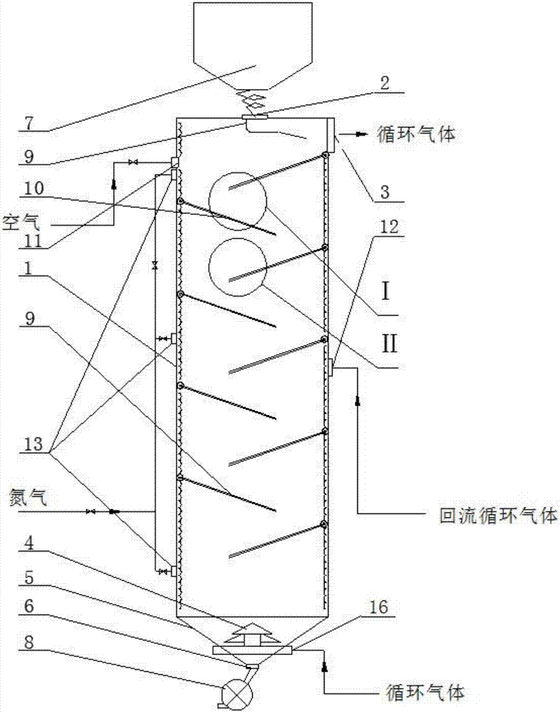
[0029] Such as figure 1 As shown, a box-type sinter waste heat recovery device according to the present invention includes a vertical box 1, a conical hopper 5, a heat exchange flow plate 10 and an air supply device 4; the top of the vertical box 1 is provided The feed port 2 is provided with a conical hopper 5 at the bottom, and the discharge port 6 is provided at the bottom of the conical hopper 5; the gas supply device 4 is provided in the conical hopper 1, and the bottom of the gas supply device 4 is provided with a circulating gas inlet 16, and the top is provided with a ring Gas outlet; the upper side of the vertical box 1 is provided with a circulating gas outlet 3; the vertical box 1 is provided with multi-layer heat exchange flow plates 10 arranged in a staggered manner along the height, forming a zigzag sinter flow channel.

[0030] The...


PUM


Abstract

The invention relates to a box-type waste heat recovering device of sintered ores. The box-type waste heat recovering device comprises a vertical-type box body, a tapered hoper, heat exchanging flowing plates and an air supply unit. A feeding port is formed in the top of the vertical-type box body, the tapper hopper is arranged at the bottom of the vertical-type box body, and a discharging port is formed in the bottom of the tapered hopper. The air supply unit is arranged in the tapered hopper, a circulating air inlet is formed in the bottom of the air supply unit, and an annular air outlet is formed in the top of the air supply unit. A circulating air outlet is formed in one side of the upper portion of the vertical-type box body, and the multiple layers of heat exchanging flowing plates arranged in a staggered mode are arranged on the vertical-type box body in the height direction to form a sintered ore flowing channel which is shaped like the Chinese character 'zhi'. The box-type waste heat recovering device of the sintered ores has the advantages of being continuous and stable in operating, good in airtightness, high in heat exchanging efficiency, small in system resistance and high in waste heat recovering quality.

Description

technical field [0001] The invention relates to the technical field of sinter waste heat recovery, in particular to a box-type sinter waste heat recovery device. Background technique [0002] The iron and steel industry is an important basic industry of the national economy. Energy consumption accounts for about 15% of the total industrial energy consumption in the country. In the process of iron and steel production, the energy consumption of the sintering process ranks second, generally accounting for 10% of the total energy consumption of iron and steel enterprises. 12%, the energy saving potential is huge. [0003] At present, the sinter is cooled by using air as a medium through a belt cooler or a ring cooler. During the cooling process, the sinter transfers heat to the flue gas, and the temperature of the flue gas is between 100°C and 400°C. Among them, the high-temperature flue gas (270°C ~ 450°C) produced in the first and second stages of the belt cooler and the ann...

Claims


Application Information

Patent Timeline
IPC IPC(8): F27D17/00
CPCF27D17/004Y02P10/25Y02P80/15
Inventor 景殿策魏振东
Owner ACRE COKING & REFRACTORY ENG CONSULTING CORP DALIAN MCC
Learn More