A Visual Monitoring Device for Burning State of Cracking Furnace

A monitoring device and cracking furnace technology, applied in the field of petrochemical industry, can solve problems such as incomplete coke cleaning, shortened device operation time, and furnace tube damage, so as to avoid anoxic or anaerobic burning and improve safety and thoroughness , to avoid the effect of local overheating

Active Publication Date: 2019-06-28
HEFEI RUISHI MEASUREMENT & CONTROL ENG TECH
View PDF1 Cites 1 Cited by
  • Summary
  • Abstract
  • Description
  • Claims
  • Application Information

AI Technical Summary

Problems solved by technology

[0004] Patent CN1282730C discloses a method for on-line monitoring of the coke burning process, which can monitor CO, CO 2 Gas concentration, although it can monitor the concentration changes of these two gases in the charred tail gas to a certain extent, but this method has the following problems: there is no O 2 Content monitoring, unable to grasp the chemical reaction rate of carbon and oxygen and the volume content of CO and CO2 in the coking tail gas, that is, unable to control the heat released during the coking process, so that local overheating of the furnace tube cannot be avoided, and the safety of the furnace tube cannot be guaranteed
In this method, excessive coking occurs when the furnace tube is slightly coked, and the coke cleaning is not thorough when it is heavily coked, which is easy to cause damage to the furnace tube, shortens the operating time of the device, and affects production efficiency
At the same time, the monitoring method of charred exhaust gas introduced in this article is manual sampling and analysis, which is usually analyzed once every half an hour, and the information feedback time is at least 2 hours. control decision

Method used


Image

  • A Visual Monitoring Device for Burning State of Cracking Furnace
  • A Visual Monitoring Device for Burning State of Cracking Furnace
  • A Visual Monitoring Device for Burning State of Cracking Furnace

Examples


Embodiment Construction

[0019] The technical solutions in the embodiments of the present invention will be clearly and completely described below in conjunction with the accompanying drawings in the embodiments of the present invention. Obviously, the described embodiments are only some, not all, embodiments of the present invention. Based on the embodiments of the present invention, all other embodiments obtained by persons of ordinary skill in the art without making creative efforts belong to the protection scope of the present invention.

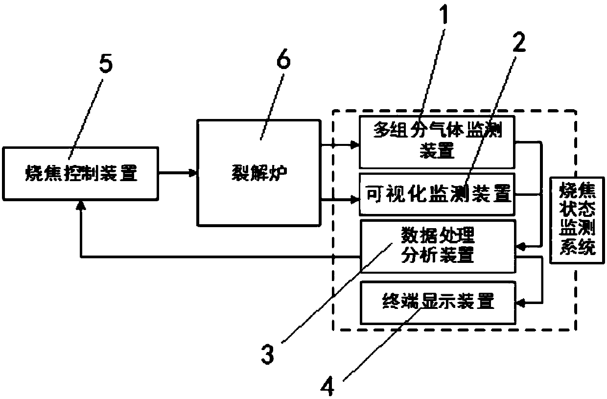
[0020] see figure 1 , a real-time monitoring device for visual cracking furnace burning state, including a multi-component gas detection device 1 installed in the control room, a data processing and analysis device 3, a terminal display device 4 and a visual monitoring device 2 installed on the cracking furnace 6, multiple The component gas detection device 1 collects the charred tail gas of the cracking furnace, analyzes the concentration of the tail gas, and o...


PUM


Abstract

The invention discloses a visualized cracking furnace burning state monitoring device. The device comprises a multi-component gas detection device, a data processing and analysis device and a terminal display device which are installed in a control room, and a visualized monitoring device which is installed on a cracking furnace. The multi-component gas detection device collects burned exhaust gas of the cracking furnace, analyzes the concentration of exhaust gas, and outputs the concentration of exhaust gas to the data processing and analysis device. The visualized monitoring device collects an infrared radiation signal of the furnace tube, analyzes the surface temperature of the furnace tube, and outputs the temperature of the furnace tube to the data processing and analysis device. The data processing and analysis device analyzes the concentration of burned exhaust gas and the surface temperature of the furnace tube, judges the burning progress, outputs a control decision to a burning control device to perform burning control, and outputs the analysis and processing result to the terminal display device. The burning process is tracked and the reaction progress of the coke layer is monitored using the visualized monitoring device and the burned exhaust gas concentration detection device. Thus, the burning effect is improved, and the service life of the device is prolonged.

Description

technical field [0001] The invention relates to a visual cracking furnace burnt state monitoring device, which belongs to the field of petrochemical industry, and specifically relates to ethylene cracking technology. Background technique [0002] Ethylene is an important chemical raw material, and the industrial level of ethylene reflects the petrochemical strength of a country. In the refining and chemical production of ethylene, in addition to the ethylene cracking reaction in the cracking furnace tube, there are various secondary cracking reactions. The secondary cracking reaction will form coke on the inner wall of the furnace tube, and the degree of coking will increase with the deepening of cracking depth. Coking in the cracking furnace will reduce the heat transfer efficiency, increase the temperature of the tube wall, easily form hot spots and shorten the service life of the furnace tube. At the same time, coking causes the inner diameter of the furnace tube to bec...

Claims


Application Information

Patent Timeline
Patent Type & Authority Patents(China)
IPC IPC(8): G05B19/04C10G9/16
CPCC10G9/16G05B19/04
Inventor 舒志峰唐磊蒋杉熊丹枫毕玉冯俊生赵晓虎仓亚军吴海滨郭刘虎
Owner HEFEI RUISHI MEASUREMENT & CONTROL ENG TECH
Why Eureka
Try Eureka