Circular ring radiation orientation method and apparatus

A radiation orientation and circular ring technology, which is applied in the direction of electrical components, inductors/transformers/magnets, circuits, etc., can solve the problems of reduced orientation magnetic field strength, inconsistent magnetic properties, and difficulty in pressing rings, so as to improve the degree of orientation and magnetism. The effect of energy and consistency improvement

Inactive Publication Date: 2017-07-21
董永安
View PDF6 Cites 3 Cited by
  • Summary
  • Abstract
  • Description
  • Claims
  • Application Information

AI Technical Summary

Problems solved by technology

This molding method is to divide the ring into several parts, and guide each part to align with the magnetic field for orientation. The biggest disadvantage of this method is that the degree of orientation is not uniform, and the joint is easy to crack, the yield is reduced, and the production cost is increased;
The above-mentioned patents all realize the orientation of ring magnets by mold rotation or magnetic field rotation. Because magnetic field rotation is difficult to achieve in engineering, mold rotation is used in reality. Because the pressure ring itself is difficult and the mold is rotating, the production efficiency and The pass rate is very low and cannot meet the needs of mass industrial production
At the same time, when producing smaller ring-shaped magnets, the intensity of the orientation magnetic field decreases, making the orientation of the magnetic powder incomplete, resulting in inconsistent magnetic properties

Method used


Image

  • Circular ring radiation orientation method and apparatus
  • Circular ring radiation orientation method and apparatus
  • Circular ring radiation orientation method and apparatus

Examples


Embodiment Construction

[0019] The following will clearly and completely describe the technical solutions in the embodiments of the present invention with reference to the accompanying drawings in the embodiments of the present invention. Obviously, the described embodiments are only some, not all, embodiments of the present invention. Based on the embodiments of the present invention, all other embodiments obtained by persons of ordinary skill in the art without making creative efforts belong to the protection scope of the present invention.

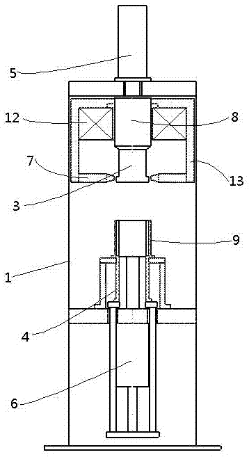
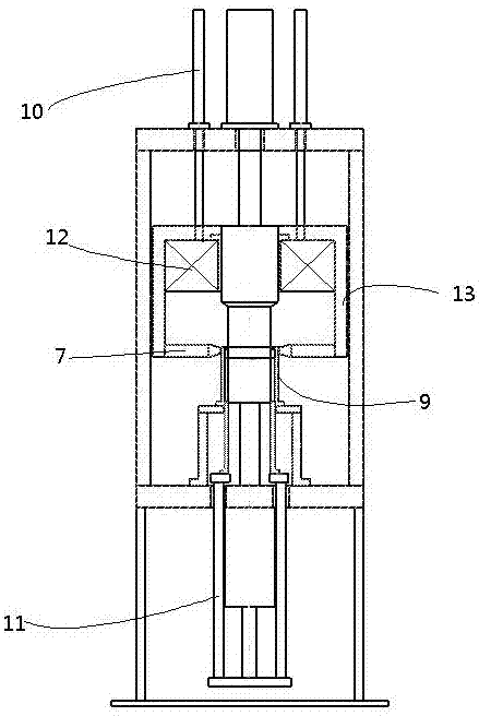
[0020] Such as Figure 1~2 As shown, a device for radiating orienting circular rings includes a frame 1, an orientation magnetic field device, an upper die punch 3 and a lower die punch 4, the upper die punch 3 and the lower die punch 4 are arranged oppositely, and both are connected with the frame 1 , the upper die punch 3 and the lower die punch 4 move through the upper oil cylinder 5 and the lower oil cylinder 6 respectively, and the cylinder bodies of the ...


PUM


Abstract

The invention relates to the technical field of magnetic powder orientation of circular magnets, in particular to a method and device for radiating orienting a circular ring. Magnetic powder is loaded into a ring-shaped mold cavity, and the magnetic powder in the ring-shaped mold cavity is oriented by an orientation magnetic field device. Orientation The orientation magnetic field of the magnetic field device exists around the annular mold cavity, which generates annular strong magnetism, and presses the magnetic powder and obtains the blank by applying force through the upper die punch and the lower die punch; The magnetic powder in the mold cavity is oriented in a ring, which improves the degree of orientation. During the molding process, the orientation magnetic field reciprocates along the axial direction of the ring mold cavity. There is a ring strong magnet in the ring mold cavity, which moves along the ring mold cavity. Not only can the magnetic powder be uniformly oriented, but also a large orientation field can be obtained when making a radiation ring with a small inner diameter or a high height, so that the magnetic properties and consistency of the radiation ring are greatly improved.

Description

technical field [0001] The invention relates to the technical field of magnetic powder orientation of circular magnets, in particular to a method and device for radially oriented circular rings. Background technique [0002] Radiation magnetic rings are widely used in the field of motors, especially in robot servo motors. The biggest technical difficulty in making the radiation ring is the orientation method of the magnetic powder in the forming stage. Restricted by physics, there are currently two main methods of magnetic field forming for radiation rings with higher aspect ratios: the first is segmented orientation and pressing, and then pressing into a whole with greater pressure. This molding method is to divide the ring into several parts, and guide each part to align with the magnetic field for orientation. The biggest disadvantage of this method is that the degree of orientation is not uniform, and the joint is easy to crack, the yield is reduced, and the production ...

Claims


Application Information

Patent Timeline
Patent Type & Authority Applications(China)
IPC IPC(8): H01F41/02B22F3/03
CPCH01F41/0266B22F3/03
Inventor 董永安李锋
Owner 董永安
Why Eureka
Try Eureka