Optically controlled optical PAM signal regeneration device

A signal regeneration and signal technology, applied in the field of optical information processing, can solve the problems of unable to PAM signal, regeneration, etc.

Inactive Publication Date: 2017-07-21
UNIV OF ELECTRONICS SCI & TECH OF CHINA
View PDF4 Cites 22 Cited by
  • Summary
  • Abstract
  • Description
  • Claims
  • Application Information

AI Technical Summary

Problems solved by technology

At present, most of the all-optical regenerator designs are aimed at traditional OOK signals, and cannot be used for the regeneration of PAM signals.

Method used


Image

  • Optically controlled optical PAM signal regeneration device
  • Optically controlled optical PAM signal regeneration device
  • Optically controlled optical PAM signal regeneration device

Examples


Embodiment

[0020] For the convenience of description, the relevant technical terms appearing in the specific implementation are explained first:

[0021] PAM (Pulse Amplitude Modulation): amplitude modulation;

[0022] NOLM (Nonlinear fiber loop mirror) nonlinear fiber environment;

[0023] MZI (Mach-Zehnder interferometer) Mach-Zehnder interferometer;

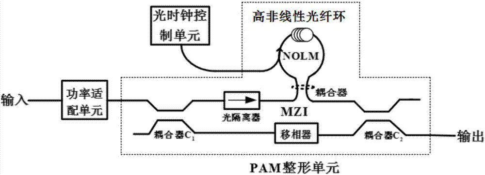
[0024] figure 1 It is a structural diagram of an optically controlled optical PAM signal regeneration device invented.

[0025] In this example, if figure 1 As shown, an optically controlled optical PAM signal regeneration device of the present invention includes: a power adaptation unit, an optical clock control unit and a PAM shaping unit;

[0026] Wherein, the power adaptation unit amplifies the input degraded optical PAM signal, so that the level of the degraded optical PAM signal is adjusted to the normal operating point of the PAM shaping unit, and then input to the PAM shaping unit;

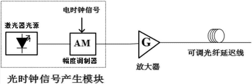
[0027] Such as figure 2 As shown, the o...

example

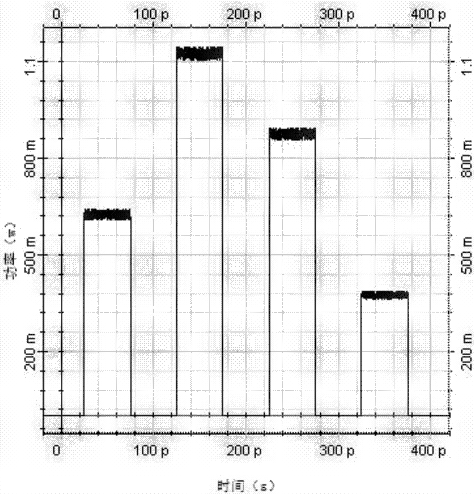
[0036] The present invention will be further described in detail below by way of examples.

[0037] Suppose the input degraded optical PAM signal such as image 3 As shown, it satisfies: the symbol rate is 10G baud, the duty cycle is 0.5, the power levels of each level are 0.375W, 0.625W, 0.875W, 1.125W, and the average normalized amplitude noise jitter

[0038] The structure of the PAM shaping unit is figure 1 As shown in the structure, in this embodiment, in order to realize the shaping of the above-mentioned 4-level degraded optical PAM signal, we select the loss coefficient as α=0.21km -1 , the nonlinear coefficient is γ=12W -1 / km high nonlinear optical fiber, on this basis, other optimization parameters adopt fiber length L=3km, phase shifter Δφ=3 / 2π, coefficients of the front and rear couplers are ρ 1 = 5.90% and ρ 2 = 98.95%. Under the optimized parameters of the above PAM shaping unit, the PAM shaping unit can perform shaping functions on four level-degraded op...


PUM


Abstract

The invention discloses an optically controlled optical PAM signal regeneration device comprising a power adapting unit, an optical clock control unit and a PAM reshaping unit, wherein the PAM reshaping unit is the core of a regenerator and is composed of a Mach-Zehnder interferometer MZI and a highly nonlinear fiber ring NOLM, for a to-be-regenerated degraded optical PAM signal, the level matching between the input degraded optical PAM signal and the PAM reshaping unit is accomplished by the power adapting unit, the optical clock signal power and the delay output by the optical clock control unit and a phase shifter in the MZI structure are adjusted, so that the PAM reshaping unit works normally, the loss coefficient, the optical fiber length, the nonlinear coefficient and other parameters of a highly nonlinear optical fiber in the NOLM structure, and the coupling coefficients of front and back couplers in the MZI structure are changed to design PAM reshaping units with different level numbers, and then the regeneration of the degraded optical PAM signal is accomplished. Therefore, the optically controlled optical PAM signal regeneration device disclosed by the invention can execute a reshaping and a re-timing function and has the advantages of flexible design of regeneration level numbers.

Description

technical field [0001] The invention belongs to the technical field of optical information processing, and more specifically relates to an optical control optical PAM signal regeneration device. Background technique [0002] In the optical fiber communication system, the optical signal is affected by factors such as fiber dispersion, fiber nonlinear effect, ASE noise accumulation of the optical amplifier, and interaction between channels during transmission, which leads to the degradation of the optical signal and ultimately limits the system and network. transmission rate and distance. Therefore, it is necessary to perform regeneration processing on the degraded signal. Although the traditional photoelectric light regeneration method is quite mature, it is difficult to meet the growing demand for higher-speed data transmission due to the existence of "electronic bottleneck". The all-optical regeneration technology of light-controlled light is considered to be the ultimate...

Claims


Application Information

Patent Timeline
Patent Type & Authority Applications(China)
IPC IPC(8): H04B10/50H04B10/54H04J3/16
CPCH04B10/503H04B10/54H04J3/16H04J3/1682
Inventor 蒋尚龙武保剑文峰邱昆
Owner UNIV OF ELECTRONICS SCI & TECH OF CHINA
Why Eureka
Try Eureka