
Partial discharge detection device and method of netted differential cable joint

A detection device and cable connector technology, applied in the field of high-voltage electricity, can solve the problems of partial discharge signal submersion, sensor interference, high-frequency harmonics, etc., and achieve the effect of solving limited detection range, increasing detection area, and wide detection range

Pending Publication Date: 2017-07-25
ZHEJIANG TUWEI ELECTRICITY TECH
View PDF0 Cites 11 Cited by
  • Summary
  • Abstract
  • Description
  • Claims
  • Application Information

AI Technical Summary

Problems solved by technology

[0007] Disadvantage 1: First, it is difficult to make a choice in the production of the capacitance detection sensor. The capacitance sensor is too small, and the range of discharge detection is small. Due to the randomness of the discharge position, the small capacitance sensor cannot completely detect the discharge position of the cable connector; If the capacitive sensor is bigger and covers a wider area, the capacitance value will also increase accordingly; when the cable discharge capacity Q value is constant, the larger the capacitance C value, the smaller the voltage V value; the detection equipment detects the voltage value V and the fixed capacitance value C , to calculate the discharge capacity Q; when the capacitance value C becomes larger, the weak partial discharge signal will not be detected
[0008] The second disadvantage of the traditional capacitive sensor is: the high voltage cable is long, the current is large, and there are many high frequency harmonics.
When the cable is working normally, the cable current harmonics will interfere with the sensor, so that the effective partial discharge signal is submerged in the cable clutter

Method used


Image

  • Partial discharge detection device and method of netted differential cable joint
  • Partial discharge detection device and method of netted differential cable joint
  • Partial discharge detection device and method of netted differential cable joint

Examples


Embodiment Construction

[0043] The following will clearly and completely describe the technical solutions in the embodiments of the present invention with reference to the accompanying drawings in the embodiments of the present invention. Obviously, the described embodiments are only some, not all, embodiments of the present invention. Based on the embodiments of the present invention, all other embodiments obtained by persons of ordinary skill in the art without making creative efforts belong to the protection scope of the present invention.

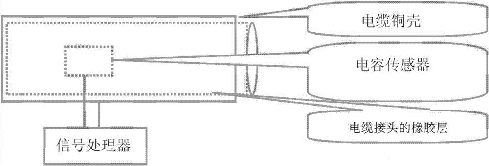
[0044] In order to overcome the problems existing in the prior art of cable partial discharge detection technology, the embodiment of the present invention proposes a mesh differential cable joint partial discharge detection device and method: the mesh differential cable joint partial discharge detection device includes a The signal detection unit and the signal processing unit at the cable joint, the signal detection unit is connected to the signal processing ...


PUM


Abstract

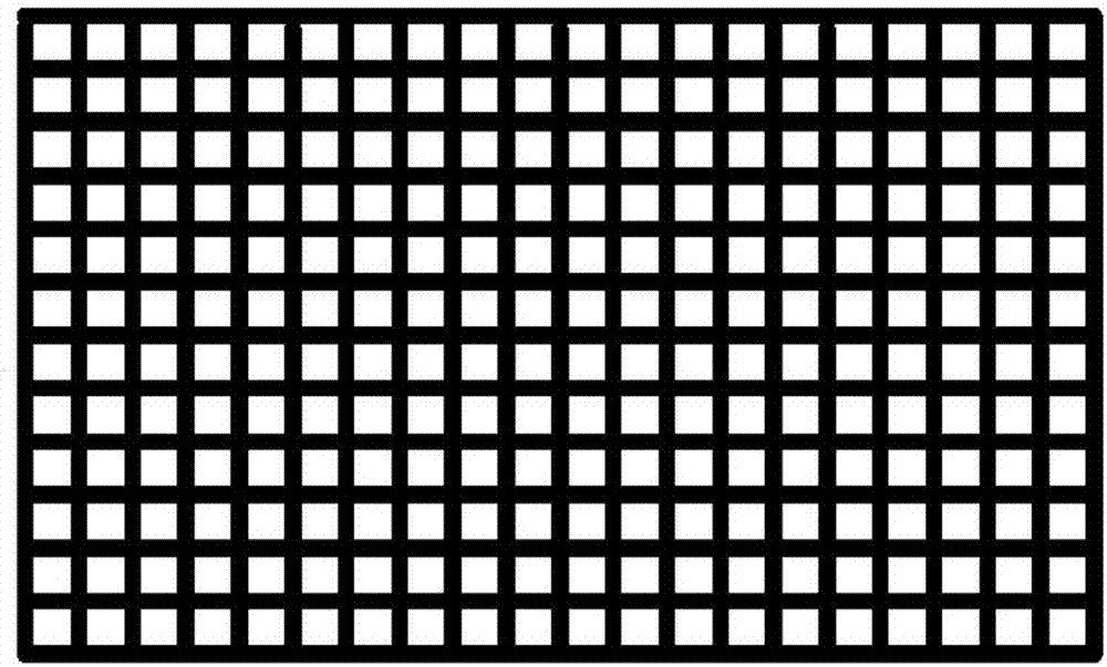
The invention relates to a partial discharge detection device and method of a netted differential cable joint. The detection device comprises a signal detection unit and a signal processing unit; both the signal detection unit and the signal processing unit are arranged in the cable joint; the signal detection unit of a netted structure employs multi-sheet distributed layout to form an angular difference; and the signal processing unit uses a difference detection principle to process multiple groups of signals transmitted by the signal detection unit. According to the partial charge detection device, a differential signal detection method is used in a capacitance sensor of the cable joint to detect partial discharge signals, the capacitance sensor arranged in the cable joint is of a netted structure, and thus, the detection area is increased, the capacitance is reduced, and the device can be installed conveniently outside a silicon rubber layer of the cable joint and inside a copper case.

Description

technical field [0001] The invention relates to the field of high-voltage electricity technology, in particular to a mesh differential cable joint partial discharge detection device and a method for detecting cable joint partial discharge using the mesh differential cable joint partial discharge detection device. Background technique [0002] The partial discharge of high-voltage XLPE cables is the main factor causing high-voltage cable accidents, and has been widely concerned for many years. The reason is mainly due to the defects in the insulating parts of the cables, which generate partial micro discharges. The discharge process accelerates the deterioration of cable insulation performance, which eventually leads to cable breakdown. How to measure the early partial discharge of cables is of great significance to the prevention of cable accidents. On the other hand, since the electric field stress of the middle joint of the power cable is relatively concentrated, it is t...

Claims


Application Information

Patent Timeline
IPC IPC(8): G01R31/12
CPCG01R31/1272
Inventor 吴建德何少林姜文天
Owner ZHEJIANG TUWEI ELECTRICITY TECH
Learn More