
Multi-cell direct-connection winding battery

A multi-unit, cell technology, applied in the construction of secondary batteries, lead-acid batteries, lead-acid batteries, etc., can solve the problems of easy deformation of the battery structure, environmental pollution, and increased internal resistance of the battery, to ensure battery consistency and battery life, avoid inconsistent internal reactions, avoid inconsistent effects of self-discharge

Active Publication Date: 2017-07-25
BSB POWER COMPANY
View PDF5 Cites 1 Cited by
  • Summary
  • Abstract
  • Description
  • Claims
  • Application Information

AI Technical Summary

Problems solved by technology

[0002] One of the disadvantages of traditional flat or traditional wound lead-acid batteries is: electrolyte stratification caused by the vertical placement of the battery plates inside; This is one of the main reasons for the decrease in battery capacity and shortened life
The second disadvantage is that the internal cells of the traditional lead-acid battery are electrically connected by lead bar tab welding, which greatly increases the internal resistance of the battery, making the battery unable to discharge at high power and charge quickly
The third disadvantage is that after the plate assembly of the traditional lead-acid battery, the assembly pressure of the battery is borne by the extrusion of the battery case. Therefore, when the traditional lead-acid battery is subjected to strong impact, the battery structure is easily deformed and fails, and the anti-vibration ability is poor.
The fourth disadvantage is that the traditional battery production has serious environmental pollution: grid lead alloy smelting and grid casting molding process, and the use of external chemical synthesis process to produce waste water containing acid and heavy metals in plate washing

Method used


Image

  • Multi-cell direct-connection winding battery
  • Multi-cell direct-connection winding battery
  • Multi-cell direct-connection winding battery

Examples


Embodiment Construction

[0043] The present application will be described in further detail below through specific embodiments in conjunction with the accompanying drawings.

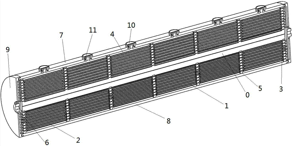
[0044] Please refer to figure 1 , the present invention proposes a multi-cell direct-connected winding battery, which includes a battery winding core, a winding battery shaft core 0, a number of insulating strips 5, a battery upper casing 7, a battery lower casing 8, and two round casting terminals 6 and two circular end caps 9, specifically described below.

[0045] The battery core includes several bipolar wound plates 1 , positive terminal wound plates 2 , negative terminal wound plates 3 and a separator 4 .

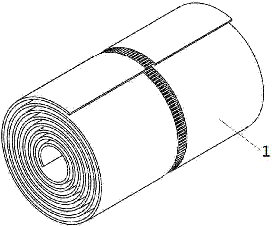
[0046] Please refer to figure 2, half of the bipolar winding plate is coated with a positive active material as a positive plate, and the other half is coated with a negative active material as a negative plate, leaving a space in the middle that is not coated with positive and negative active materials for each unit...


PUM


Abstract

The invention discloses a multi-cell direct-connection winding battery. A battery roll core comprises a bipolar winding plate, a positive terminal winding pole plate, a negative terminal winding pole plate and a separator, wherein a positive active substance is coated on half of the bipolar winding plate and is used as a positive pole plate, a negative active substance is coated on the other half of the bipolar winding plate and is used as a negative pole plate, a spacing region is reserved at the middle part, is not coated with the positive active substance and the negative active substance and is used for electrical connection among cells, a positive active substance is coated on the positive terminal winding pole plate and is used as a positive pole plate, a region is reserved at one edge, is not coated with the positive active substance and is used as a positive output end of the battery roll core, a negative active substance is coated on the negative terminal winding pole plate and is used as a negative pole plate, a region is reserved at one end, is not coated with the negative active substance and is used as a negative output end of the battery roll core, and the bipolar winding plate, the positive terminal winding pole plate, the negative terminal winding pole plate and the separator are arranged at an axial core of the winding battery in a rolling way.

Description

technical field [0001] The present application relates to the field of storage batteries, in particular to a multi-cell direct-connected winding battery. Background technique [0002] One of the disadvantages of traditional flat or traditional wound lead-acid batteries is: electrolyte stratification caused by the vertical placement of the battery plates inside; This is one of the main reasons for the decrease in battery capacity and shortened life. The second disadvantage is that the internal cells of the traditional lead-acid battery are electrically connected by lead bar tab welding, which greatly increases the internal resistance of the battery, making the battery unable to discharge at high power and charge quickly. The third disadvantage is that after the plate assembly of the traditional lead-acid battery, the assembly pressure of the battery is borne by the extrusion of the battery case. Therefore, when the traditional lead-acid battery is subjected to a strong impac...

Claims


Application Information

Patent Timeline
Patent Type & Authority Applications(China)
IPC IPC(8): H01M10/12H01M10/18
CPCH01M10/123H01M10/125H01M10/18Y02E60/10Y02P70/50
Inventor 韩祖孟刘天荣
Owner BSB POWER COMPANY
Learn More