Centrifugal flue gas desulfurization and denitration dedusting tower

A technology of desulfurization, denitrification, and dust removal tower, which is applied in the fields of environmental protection and resource recycling, and can solve problems such as impact effects, secondary pollution, and uneven spraying, and achieve the effects of simple and convenient maintenance, reduced operating costs, and uniform spraying

Pending Publication Date: 2017-07-28
麦冠华
View PDF0 Cites 1 Cited by
  • Summary
  • Abstract
  • Description
  • Claims
  • Application Information

AI Technical Summary

Problems solved by technology

[0003] In the existing flue gas desulfurization, denitrification and dust removal tower, the flue gas enters from the bottom of the treatment tower through the induced draft fan, and then there are multi-layer mist spraying devices in the tower for continuous spraying to neutralize the sulfur and nitrogen oxides in the flue gas, but Usually, due to the large flow rate and fast flow rate of industrial gas, it is difficult to achieve the neutralization effect in a short time; such a large flow rate of flue gas enters the treatment tower, and it is easy to form a blind area and eccentricity of the air flow in the tower, resulting in uneven spraying and affecting the spray

Method used


Image

  • Centrifugal flue gas desulfurization and denitration dedusting tower
  • Centrifugal flue gas desulfurization and denitration dedusting tower
  • Centrifugal flue gas desulfurization and denitration dedusting tower

Examples


Embodiment Construction

[0031] In order to allow those skilled in the art to understand the present invention more clearly and intuitively, the present invention will be further described below in conjunction with the accompanying drawings.

[0032] like Figure 1-5 Shown is a preferred embodiment of the invention.

[0033] The centrifugal flue gas desulfurization, denitrification and dedusting tower of this embodiment includes:

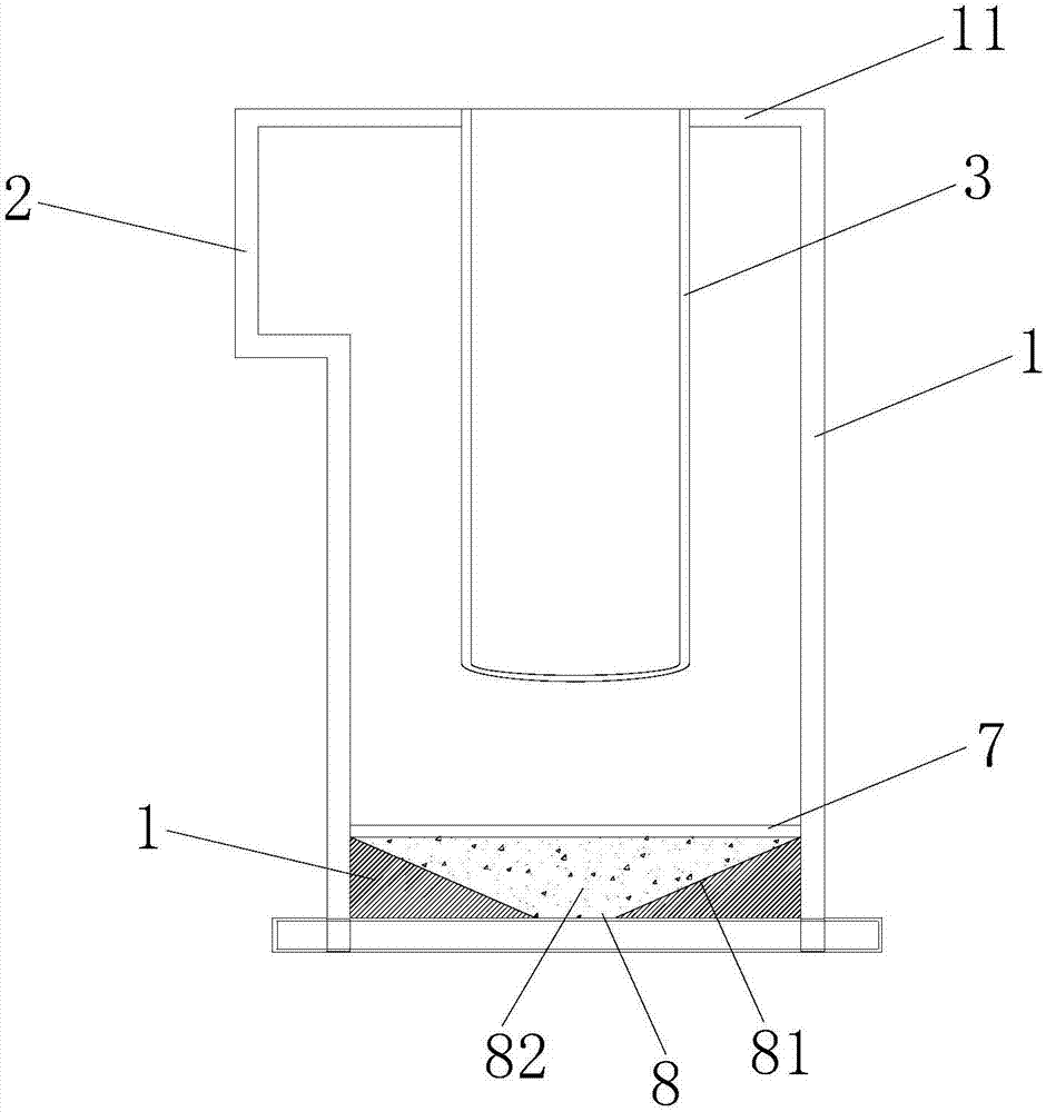
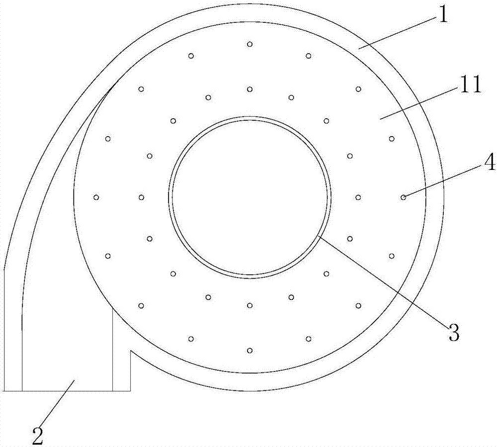
[0034] The outer tower body 1 is cylindrical, and the tower chamber of the outer tower body 1 is a flue gas desulfurization, denitrification, and dust removal treatment area, and the bottom of the outer tower body 1 has a water outlet;

[0035] The flue gas input pipe 2, as the intake pipe of the flue gas in the outer tower body 1, is arranged on the tower top side wall of the outer tower body 1 and communicates with the tower cavity. There is an included angle of 45° between them, so that after the flue gas enters the tower cavity, it is transported against the inner wal...


PUM


Abstract

The invention provides a centrifugal flue gas desulfurization and denitration dedusting tower, which includes an outer tower body, a flue gas inlet tube, an inner cylinder and a spraying device. The flue gas inlet tube is arranged on a tower top side wall of the outer tower body, and forms an angle of 45 degrees with a tangent line of the outer tower body's outer wall surface, so that flue gas can form cyclone after entering the tower cavity. The inner cylinder is hung at the top of the outer tower body, the lower end opening of the inner cylinder is provided with a guide sleeve for flow guiding. The spraying device is equipped with a plurality of spray guns, the liquid sprayed by nozzles of the spray guns is used for desulfurization, denitration and dedusting treatment of external flue gas, and the spray guns are detachably and evenly inserted to the tower top between the outer tower body and the inner cylinder through a sealed insertion seat. According to the invention, the flue gas can form cyclone, the disposed inner cylinder makes the rotation standing time of flue gas in the tower cavity not less than 4 times longer than the original and achieve uniform stirring. The spraying device adopts a tower top layout, spraying can be more uniform, also the spray guns of the spraying device are mounted through the sealed insertion seat, inspection and repair can be very simple and convenient, and the nozzles are not blocked easily.

Description

technical field [0001] The invention relates to a centrifugal flue gas desulfurization, denitrification and dust removal tower, which belongs to the technical field of environmental protection and resource recycling. Background technique [0002] There are many processes for flue gas dedusting, desulfurization and denitrification in industrial furnaces in my country. The absorbents used are different, the process flow is different, the structure of the equipment is different, and the effect is completely different. Especially in recent years, with the improvement of my country's air pollutant discharge standards and scientific and technological progress, a considerable part of the process methods and equipment have been eliminated, and new dust removal, desulfurization, and denitrification processes and equipment continue to emerge. [0003] In the existing flue gas desulfurization, denitrification and dust removal tower, the flue gas enters from the bottom of the treatment ...

Claims


Application Information

Patent Timeline
IPC IPC(8): B01D53/78B01D53/60B01D47/06B01D50/00
CPCB01D47/06B01D53/60B01D53/78B01D2258/0283B01D50/40
Inventor 麦冠华
Owner 麦冠华
Why Eureka
Try Eureka