Deep high-ground-temperature roadway heat-insulation lining structure and construction method thereof

A technology of high ground temperature and roadway, applied in tunnel lining, shaft lining, tunnel, etc., can solve the problems of unguaranteed thermal insulation effect, failure of thermal insulation materials, low strength, etc., achieve excellent thermal insulation and fire protection effect, and reduce the loss of material strength. , Improve the effect of thermal insulation

Active Publication Date: 2017-07-28
ANHUI UNIV OF SCI & TECH
View PDF22 Cites 8 Cited by
  • Summary
  • Abstract
  • Description
  • Claims
  • Application Information

AI Technical Summary

Problems solved by technology

At present, the heat insulation method used is often to directly spray the heat insulation material on the roadway rock wall. fail
Related technologies have also made corresponding improvements. The patent No. 201510092058.8 discloses a heat-insulating and heat-dissipating lining structure for high-temperature tunnels. The heat dissipation effect evacuates the heat out of the lining structure, but many pipe networks are arranged in the structure, and the strength of the foam concrete is lower than that of the general concrete lining structure, which cannot well adapt to the high ground pressure of the deep tunnel; the patent No. 201010142253.4 discloses the mine The heat-insulating and fire-proof composite wall of the roadway is made of a certain number of heat-insulating and fire-proof co

Method used


Image

  • Deep high-ground-temperature roadway heat-insulation lining structure and construction method thereof
  • Deep high-ground-temperature roadway heat-insulation lining structure and construction method thereof
  • Deep high-ground-temperature roadway heat-insulation lining structure and construction method thereof

Examples


Embodiment Construction

[0033] In order to make the objectives, technical solutions, and advantages of the embodiments of the present invention clearer, the technical solutions in the embodiments of the present invention will be described clearly and completely in conjunction with the accompanying drawings in the embodiments of the present invention. Obviously, the described embodiments It is a part of the embodiments of the present invention, not all the embodiments. Based on the embodiments of the present invention, all other embodiments obtained by those of ordinary skill in the art without creative work shall fall within the protection scope of the present invention.

[0034] Attached Figure 1 to Figure 6 To further explain the present invention:

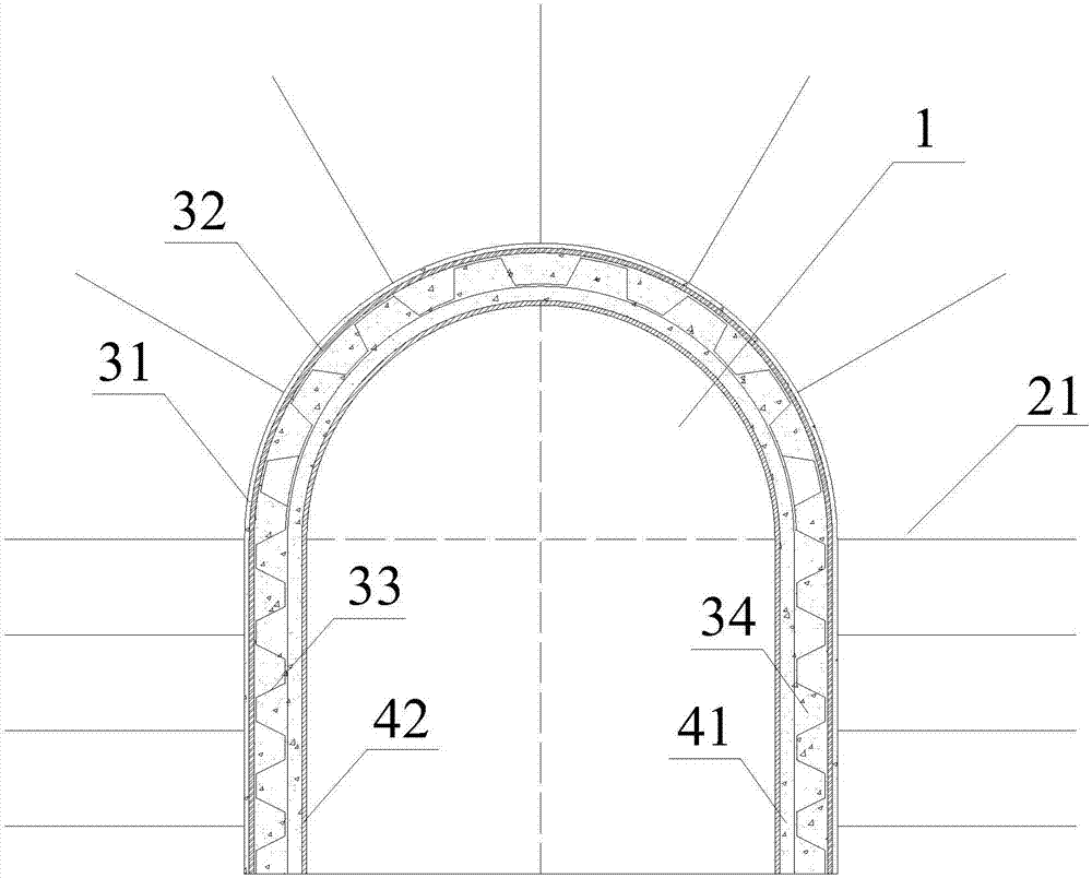
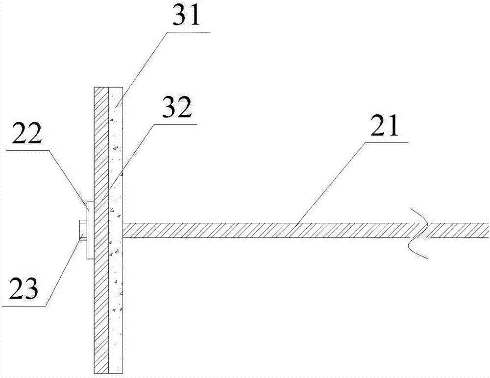
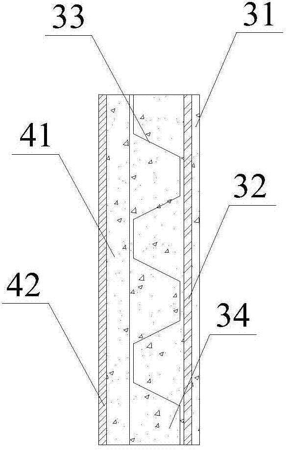
[0035] The heat-insulating lining structure of deep high ground temperature roadway according to the present invention, such as Image 6 As shown, the grouting insulation ring 2, the primary lining insulation layer 3 and the secondary lining insulation la...


PUM


Abstract

The invention discloses a deep high-ground-temperature roadway heat-insulation lining structure and a construction method thereof. The lining structure comprises a grouting heat-insulation ring, a primary lining heat-insulation layer and a secondary lining heat-insulation layer. Firstly, a heat-insulation grout material is injected through a hollow grouting anchor rod to form a grouting heat-insulation ring; the primary lining heat-insulation layer is distributed to form a primary support, wherein the primary lining heat-insulation layer comprises a first jet ceramsite concrete layer, a reinforcing mesh layer, a metal support and a second jet ceramsite concrete layer; after roadway deformation is stabilized, the secondary lining heat-insulation layer is constructed, and construction of the structure is completed, wherein the secondary lining heat-insulation layer comprises a third jet ceramsite concrete layer and a heat-insulation plate. By means of the structure and existing common support means and according to the current situation that deep mining high-temperature damage is severe, the stability of a roadway support structure is ensured by reasonably improving supporting materials and increasing the heat-insulation plates; by means of multiple heat-insulation measures, heat is effectively prevented from spreading into a roadway, and the application and popularization value is good.

Description

Technical field [0001] The invention relates to the technical field of deep roadway lining structures, in particular to a deep high ground temperature roadway heat insulation lining structure and a construction method thereof. Background technique [0002] At present, with the rapid development of my country's national economy, coal plays an important role in the field of providing energy for our country and is the "real food" of industry. However, shallow resources are increasingly depleted, and the depth of mining is increasing, and the problem of high ground temperature has gradually become a major issue that needs to be resolved. According to the measurement, the geothermal gradient in my country generally ranges from 30 to 50°C / km. In some areas such as near faults or abnormal local areas with high thermal conductivity, the geothermal gradient sometimes reaches 200°C / km. It can be seen that in a mine with a depth of more than one thousand meters, the temperature in the tunn...

Claims


Application Information

Patent Timeline
IPC IPC(8): E21D11/38E21D11/00E21D11/10C04B28/00
CPCE21D11/006E21D11/107E21D11/38E21D11/383E21D11/385C04B28/00C04B14/02C04B22/00C04B14/10C04B14/06C04B18/24C04B14/22C04B18/027C04B18/08C04B16/0633C04B14/043
Inventor 姚韦靖庞建勇
Owner ANHUI UNIV OF SCI & TECH
Why Eureka
Try Eureka