
High-frequency pulse injection device

A high-frequency, pulsed technology, applied to ramjet engines, combustion methods, combustion equipment, etc., can solve problems such as difficult to control pressure growth, difficult to meet requirements, long mixing of fuel and incoming flow, etc., to achieve low processing difficulty, The effect of simple structure and long and narrow shape

Active Publication Date: 2017-07-28
YINGSHANG LONGYUYANG IND & TRADE
View PDF6 Cites 4 Cited by
  • Summary
  • Abstract
  • Description
  • Claims
  • Application Information

AI Technical Summary

Problems solved by technology

Among them, passive mixing enhancement is currently widely used, mainly including physical slopes, concave cavities, tower structures, etc., and there are mainly the following problems: (1) It can achieve macroscopic and large-scale turbulence, but the microscopic turbulence is insufficient To achieve a high degree of mixing of fuel and incoming flow; (2) The mixing of fuel and incoming flow has a relatively long process, which is difficult to meet the requirements; (3) It is difficult to control the impact of pressure growth caused by heat release

Method used


Image

  • High-frequency pulse injection device
  • High-frequency pulse injection device
  • High-frequency pulse injection device

Examples


Embodiment Construction

[0027] The present invention will be further described in detail below in conjunction with the accompanying drawings and specific embodiments.

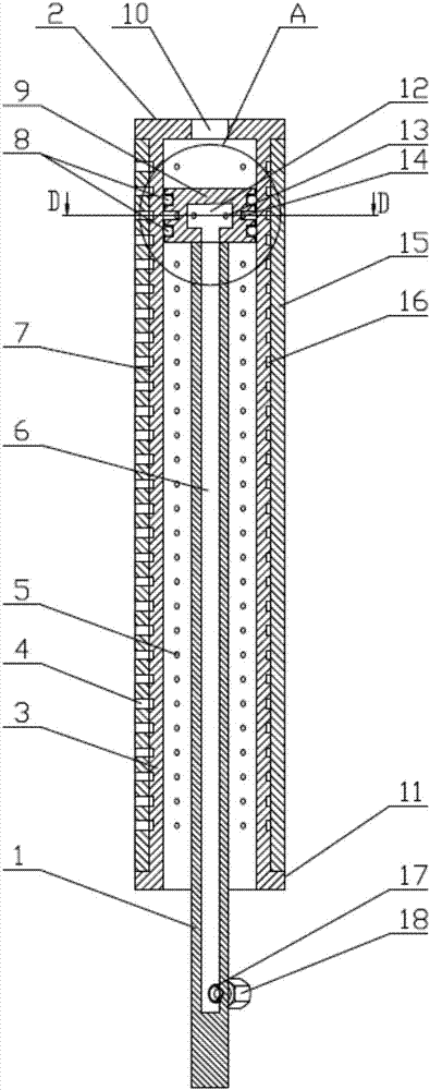
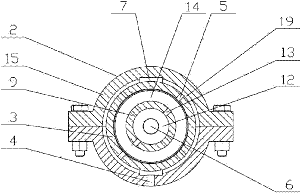
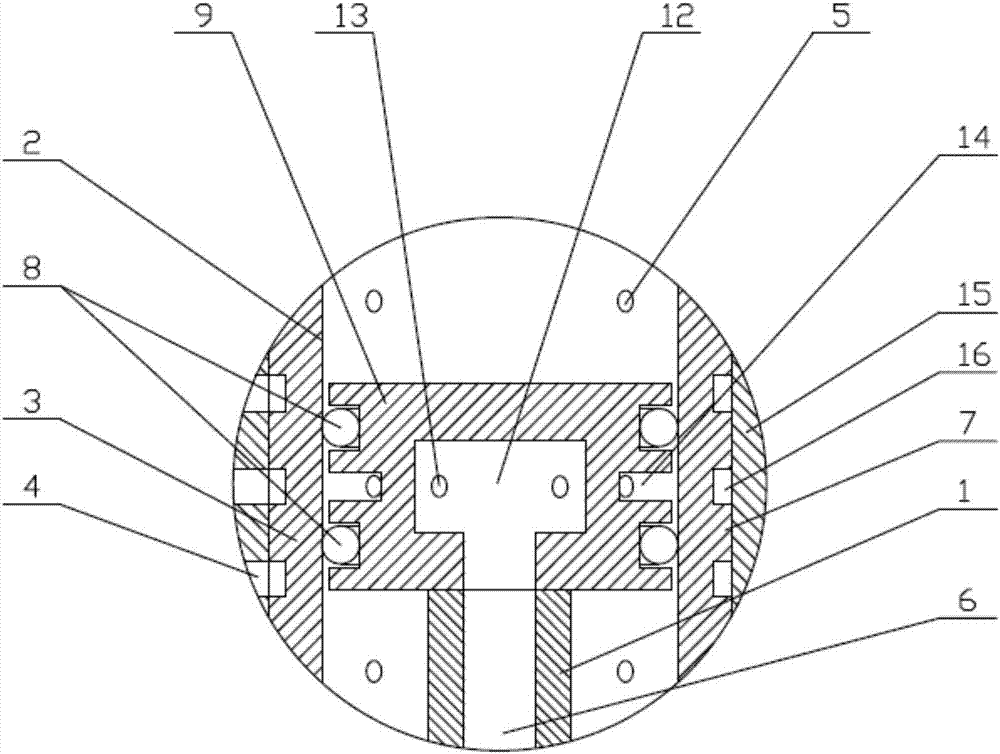
[0028] Figure 1-5 As shown, a specific implementation of the present invention is: a high-frequency pulse injection device, including a cylinder 2 and a piston 9, the piston rod 1 is connected to the servo motor through a four-bar mechanism, and the front end of the cylinder 2 is provided with a through The hole 10 is a composite structure as a whole, and is composed of a rectifying cylinder 3 and a rectifying sleeve 15; the piston rod 1 is a hollow columnar structure, the upper end is welded with the piston 9, and the bottom end is sealed; the piston rod 1 is provided at a closed position near the bottom end. There is an oil injection hole 17 communicating with the columnar hollow 6, and a threaded transition joint 18 is provided on the oil injection hole 17; the piston 9 is a blind hole structure with a cavity 12, and the cavity 12...


PUM


Abstract

The invention provides a high-frequency pulse injection device and relates to the technical field of stamping type engines. The front end of a cylinder body is provided with a through hole, and the cylinder body is of a compound structure as a whole and is composed of a rectification barrel and a rectification sleeve in a wedged and sleeved manner; a piston rod is of a hollow pillar-shaped structure, the upper end of the piston rod is welded to a piston, and the bottom end of the piston rod is sealed; the position, close to the bottom end closed position, of the piston rod is provided with an oil injection hole communicating with the pillar-shaped hollow portion, and the oil injection hole is provided with a threaded transition connector; the piston is of a blind hole structure with a cavity, the cavity communicates with the pillar-shaped hollow portion, a groove in the middle of the piston is an injection hole slot, and the injection hole slot is internally provided with first injection through holes communicating with the cavity; the outer side of the rectification barrel is symmetrically provided with two columns of positioning platforms with rectangular cross sections; and second injection through holes in the inner wall of the rectification barrel communicate with second rectification slots of the rectification sleeve, the second rectification slots of the rectification sleeve are in one-to-one correspondence with the second injection through holes in the rectification barrel, the rectification sleeve is provided with third uniform injection through holes in columns, and the third injection through holes communicate with first rectification slots and the second rectification slots. The high-frequency pulse injection device is used for the stamping type engines.

Description

technical field [0001] The invention relates to the technical field of ramjet engines. Background technique [0002] The flow rate of scramjet engine is very fast, and the residence time of fuel is often on the millisecond level. For liquid hydrocarbon fuel, the process of droplet breakup, atomization and evaporation must also be considered, which increase the time required for the fuel to achieve a complete chemical reaction. The time required and the length of the combustion chamber. Restricted by conditions such as engine structure and quality, the length of the combustion chamber cannot be very long, so it is difficult to achieve complete mixing of fuel and incoming flow. Supersonic combustion is generally a diffusion flame, and the mixing effect directly determines the combustion performance of the combustion chamber. Therefore, fuel injection and blending technology has always been the key technology in scramjet research. [0003] At present, the fuel injection tech...

Claims


Application Information

Patent Timeline
IPC IPC(8): F02K7/14F23R3/28
CPCF02K7/14F23R3/28
Inventor 高宏力刘祺邓维鑫杨顺华
Owner YINGSHANG LONGYUYANG IND & TRADE
Learn More