Automatic control industrial kiln burning machine movement rack system

A burner and mobile rack technology, applied in the direction of furnace control devices, furnaces, furnace components, etc., can solve problems such as inability to evacuate in time

Active Publication Date: 2017-07-28
中关村科技租赁股份有限公司
View PDF8 Cites 2 Cited by
  • Summary
  • Abstract
  • Description
  • Claims
  • Application Information

AI Technical Summary

Problems solved by technology

[0004] The purpose of the present invention is to overcome the deficiencies of the existing technology, and the purpose is to provide an automatic control system for moving the industrial kiln burner, so as to solve the problem that the burner on the existing industrial kiln cannot be evacuated in time.

Method used


Image

  • Automatic control industrial kiln burning machine movement rack system
  • Automatic control industrial kiln burning machine movement rack system
  • Automatic control industrial kiln burning machine movement rack system

Examples


Embodiment

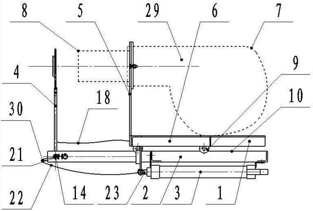
[0028] like Figure 1-5 As shown, an automatic control industrial kiln burner mobile rack system of the present invention includes a burner installation trolley 1, an underframe 2, a cylinder 3 and a blocking device 4, and the burner installation trolley 1 is provided with a stand 5 and a translation rack 6. The vertical frame 5 is vertically welded on the front end of the translation frame 6 to support the burner 8 of the burner 7. The bottom of the translation frame 6 is provided with a pulley 9, and the bottom frame 2 is provided with a guide rail 10 that matches the pulley 9. The cylinder 3 It is arranged on the bottom of the chassis 2 to push the burner installation trolley 1 and the burner 7 to move back and forth; the burner 7 generally includes a burner 8 and a fuselage 29 inserted into the furnace.

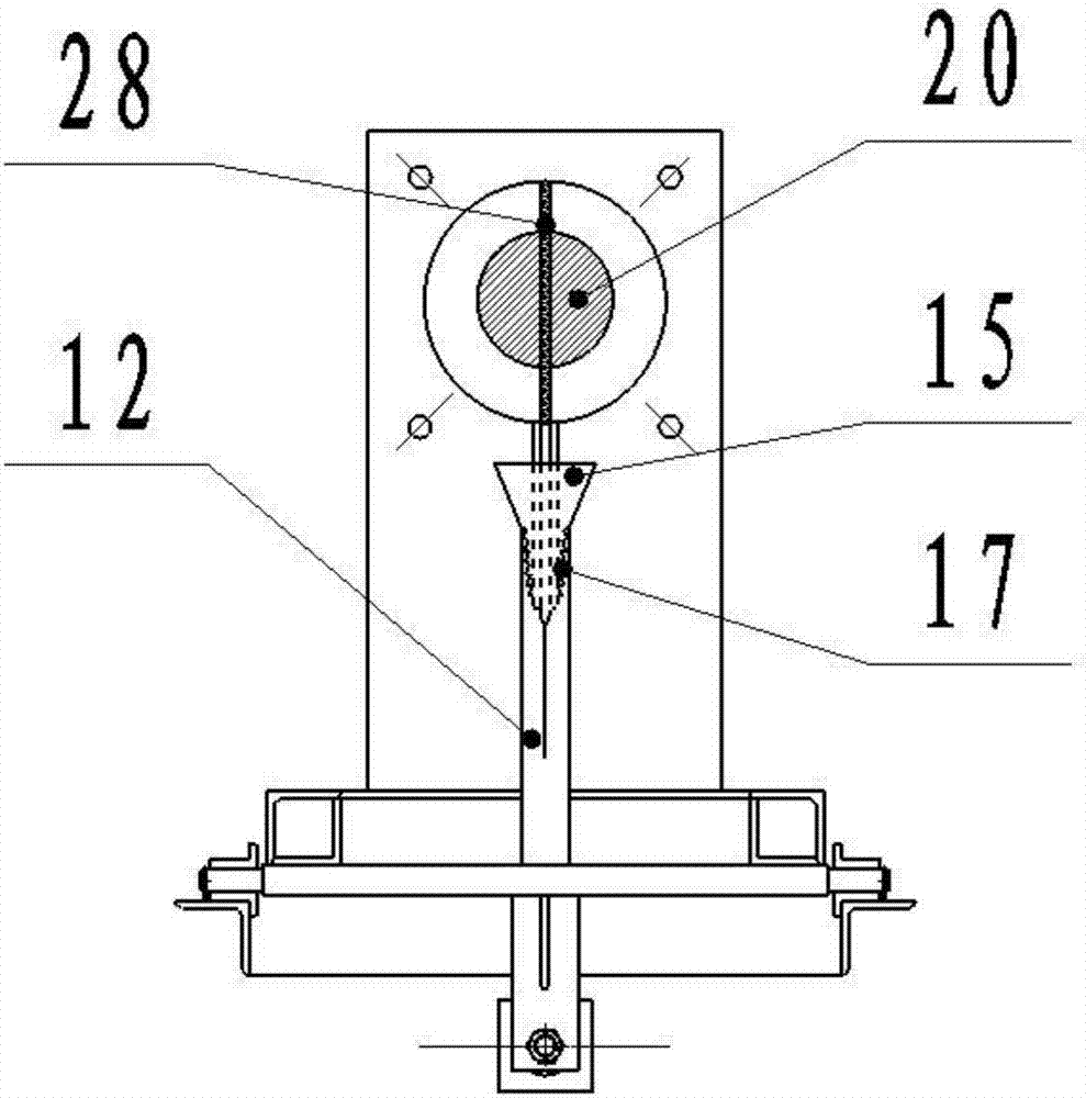
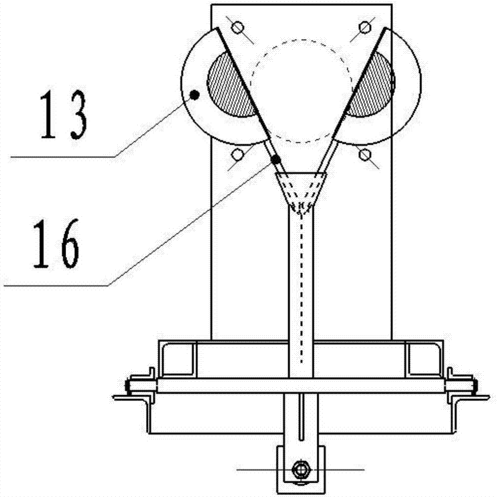
[0029] The front part of the chassis 2 is provided with a blocking device chute 11, and the blocking device 4 includes a moving guide cylinder 12 and a blocking semicircl...


PUM


Abstract

The invention discloses an automatic control industrial kiln burning machine movement rack system. The automatic control industrial kiln burning machine movement rack system comprises a burning machine installation trolley, a bottom rack, an air cylinder and a plugging device, wherein the burning machine installation trolley is provided with a stand rack and a horizontal movement rack, the stand rack is perpendicularly welded to the front end of the horizontal movement rack to be used for supporting the burner of the burning machine, sliding wheels are arranged at the bottom of the horizontal movement rack, guide rails used in cooperation with the sliding wheels are arranged on the bottom rack, and the air cylinder is arranged at the bottom of the bottom rack to push the burning machine installation trolley and a burning machine to move forward or backward. The automatic control industrial kiln burning machine movement rack system solves the problem that the burning machine of an existing industrial kiln cannot be withdrawn in time when needing withdrawing.

Description

technical field [0001] The invention relates to the field of a burner for an industrial kiln, in particular to an automatic control moving frame system for an industrial kiln burner. Background technique [0002] In the field of industrial furnaces, gas and oil heating are widely used. Burners are the main equipment in gas and oil heating devices. Currently, burners are fixedly installed in industrial furnaces, which has great disadvantages in production. If there is a sudden equipment failure, the high-temperature hot air of the equipment will easily flow back to the burner, and the burner will be burned out from time to time. In addition, when the furnace temperature is too high, the burner cannot be withdrawn in time, which will easily lead to damage. [0003] Moreover, in the existing equipment, after the burner is manually withdrawn from the furnace body, if the burner insertion port cannot be blocked in time, the burner insertion port on the furnace body will backfire...

Claims


Application Information

Patent Timeline
Patent Type & Authority Applications(China)
IPC IPC(8): F27D99/00F27D19/00
CPCF27D19/00F27D99/0033F27D99/0073
Inventor 李永芬
Owner 中关村科技租赁股份有限公司
Why Eureka
Try Eureka