
Self-driven optical excitation gas sensor

A gas sensor and gas sensor technology, applied in the direction of material resistance, can solve the problems of energy loss, inability to maintain continuous power consumption of heating elements, increase costs, etc., and achieve the effect of reducing loss

Inactive Publication Date: 2017-07-28
DALIAN UNIV OF TECH
View PDF10 Cites 5 Cited by
  • Summary
  • Abstract
  • Description
  • Claims
  • Application Information

AI Technical Summary

Problems solved by technology

However, because this power supply mode causes a lot of energy loss in the process of collection and storage, its high voltage and low current characteristics have high requirements on the energy collection circuit, which increases the cost. At the same time, the collection efficiency is low, and the continuous power consumption of the heating element cannot be maintained. , thus greatly limiting the development and application of self-driving sensors

Method used


Image

  • Self-driven optical excitation gas sensor
  • Self-driven optical excitation gas sensor
  • Self-driven optical excitation gas sensor

Examples


Embodiment 1

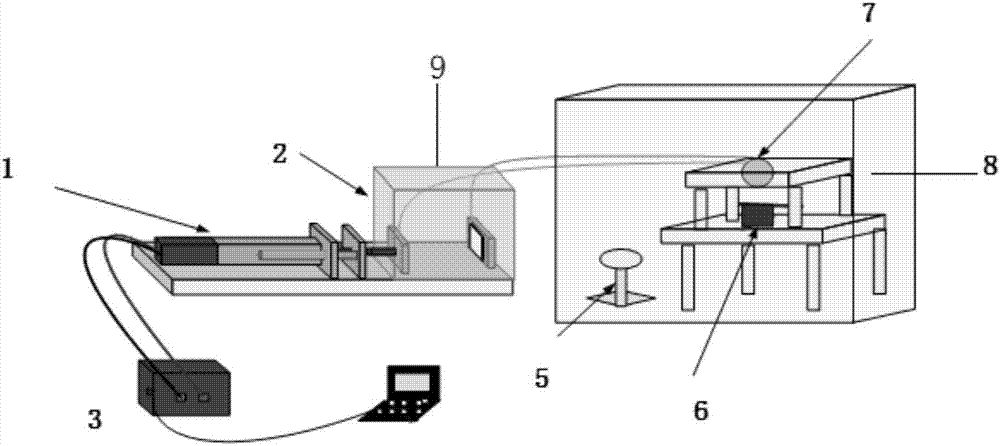
[0018] see figure 1 As shown, this embodiment provides a self-driven light-excited gas sensor, including a triboelectric nanogenerator, a packaging component, a light source, and a gas sensor. The triboelectric nanogenerator is electrified by friction, and the electric signal generated is used as an energy source, which is directly used for power supply of LED lamps, including friction materials, Faraday covers, electric motors, and drivers; the packaging assembly encapsulates the gas sensor and the light source In a sealed space, including an air inlet and a heater; the light source is a single light source with a fixed wavelength range; the gas sensor is a semiconductor gas sensitive material gas sensor, and the thickness of the sensitive material coating is 0.4-0.5 mm.

[0019] Wherein, the friction material component of the friction nano generator is titanium dioxide nano array.

[0020] The titanium dioxide nano-array is prepared by hydrothermal method and high-temperat...

Embodiment 2

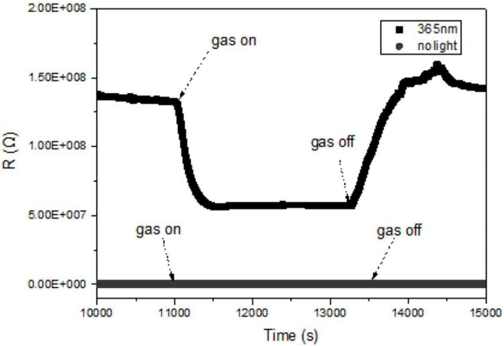
[0031] The difference between the technical solution of this embodiment and Embodiment 1 is that the material of the semiconductor gas sensor and the test gas are different. This embodiment only describes the different parts, and the same parts will not be repeated. The material of the semiconductor gas sensor selected in this embodiment is WS 2 Nanomaterials, test gas is 10ppm NH 3 . image 3 WS under room temperature conditions with 365-400nm light excitation and no light conditions 2 Gas sensor for 10ppm NH 3 Comparison chart of the resistance change curve.

Embodiment 3

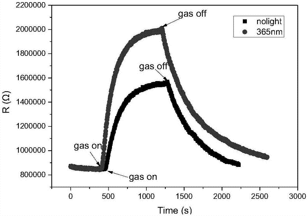
[0033] The difference between the technical solution of this embodiment and Embodiment 2 is that the parameter setting of the driver of the friction generator and the light source test selected are different. This embodiment only describes the different parts, and the same parts will not be repeated. The light source selected in this embodiment is a bead-type LED light source with a wavelength of 940nm and a rated power of 24mW. Figure 4 WS under room temperature conditions with a wavelength of 940nm light excitation and under no light conditions 2 Gas sensor for 10ppm NH 3 Comparison chart of the resistance change curve.


PUM

PropertyMeasurementUnit
thicknessaaaaaaaaaa
thicknessaaaaaaaaaa
sizeaaaaaaaaaa

Abstract

The invention belongs to the technical field of electronic elements and relates to a self-driven optical excitation gas sensor. The self-driven optical excitation gas sensor comprises an environment vibrational energy generation unit, a packaging component, a light source and a gas sensitivity sensor. The environment vibrational energy generation unit comprises an environment vibration generator, a motor, a Faraday cage and a driver, the environment vibration generator is arranged in the Faraday cage, the motor is controlled by the driver to drive the environment vibration motor to perform vibration movement, the vibrational energy of the shielding environment is acquired, a produced electric signal is used as an energy source and is used for providing electric energy for an LED lamp; the packaging component packages the gas sensitivity sensor and the light source in one same closed space, the light source is arranged on the vertical plane of the gas sensitivity sensor, and the gas sensitivity sensor is a semiconductor gas sensitive material sensor. The electric energy produced by a self-powdered friction nano generation system is used to provide the electric energy for the light source directly, the loss of the energy is reduced, and the semiconductor gas sensor is self-driven without the help of the stored energy of a battery.

Description

technical field [0001] The invention relates to the field of electronic components, in particular to a self-driven light-excited gas sensor. Background technique [0002] Semiconductor gas sensors play an important role in industrial exhaust, indoor environment detection and other fields, and have a broad application background. However, the semiconductor gas sensor is not ideal for gas characteristics at room temperature. It is usually necessary to install a heating wire on the gas sensor element to increase the working temperature of the element, overcome the high reaction activation energy of the semiconductor material, and enhance the sensitivity of the gas sensor. . However, there are many deficiencies and defects in improving the performance of components through heating, which not only increases energy consumption, but also easily detonates flammable gases in the environment, causing safety hazards. At the same time, it will also deteriorate the performance of the c...

Claims


Application Information

Patent Timeline
Patent Type & Authority Applications(China)
IPC IPC(8): G01N27/04
Inventor 李晓干顾丁奚伊李明泽王兢陈宇鹏
Owner DALIAN UNIV OF TECH
Learn More