
Test clamp of 10kV switch cabinet current transformer

A technology for current transformers and test fixtures, which is applied to instruments, measuring electrical variables, measuring devices, etc., can solve the problems of screws being in the blind area of ​​the field of view, difficulty in clamping operation, low test efficiency, etc., so as to reduce the number of test wiring and save the test. time, the effect of ensuring the reliability of power supply

Pending Publication Date: 2017-07-28
YINGKOU ELECTRIC POWER SUPPLY COMPANY OF STATE GRID LIAONING ELECTRIC POWER SUPPLY +1
View PDF0 Cites 0 Cited by
  • Summary
  • Abstract
  • Description
  • Claims
  • Application Information

AI Technical Summary

Problems solved by technology

The internal space of the cabinet is narrow, only the arm can be extended in, and the screw is in the blind area of ​​vision, which makes it difficult to clamp the wire, and the wire clip is easy to fall off, posing a safety hazard
In addition, due to the short exposure of the pile head screw and the small contact surface, the large contact resistance and the difficulty in raising the current during the high-current test will cause the test to fail, and the clamping operation needs to be repeated, which reduces the test efficiency.
It can be seen that the structure and operation limitation of the traditional fixture are the main reasons for the low test efficiency, and it is necessary to develop a new fixture to replace the traditional fixture, so as to improve the test efficiency

Method used


Image

  • Test clamp of 10kV switch cabinet current transformer
  • Test clamp of 10kV switch cabinet current transformer

Examples


Embodiment Construction

[0018] Below in conjunction with accompanying drawing, the present invention is described in further detail:

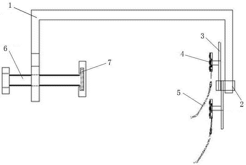
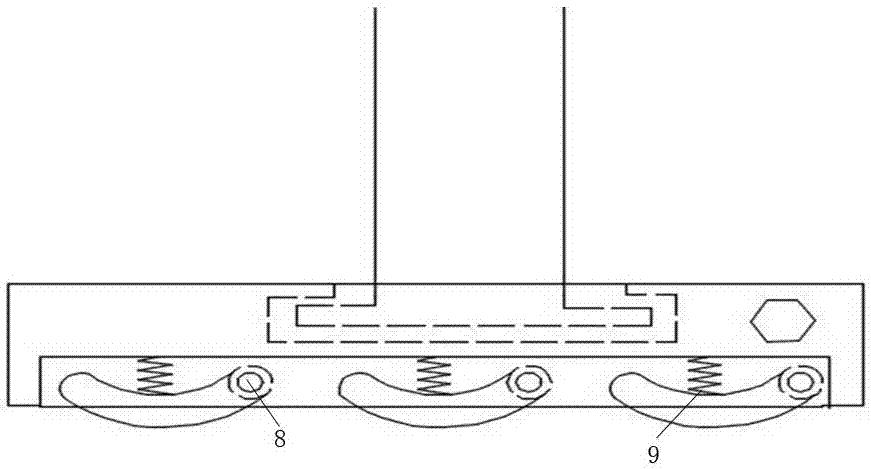
[0019] like figure 1 As shown, a 10kV switch cabinet current transformer test fixture of the present invention includes an inverted U-shaped crank arm 1, and the inverted U-shaped crank arm 1 is made of Bakelite with good insulation and easy processing. A rotatable double-arm clamp 3 is fixed with a bolt 2 at the front end of the crank arm, and the head of the clamp is a plurality of copper spring contacts 4 . like figure 2 As shown, the contacts are multi-row contacts, one end is fixed on the movable shaft 8, and the other end is supported by a spring 9. The contact can be connected to the test cable 5 . A screw handle 6 is installed at the rear end of the crank arm, and an insulating pad 7 is installed at the bottom of the screw rod.

[0020] When the present invention is in use, the copper contact at the front end is pressed on the wiring aluminum bar of the c...


PUM


Abstract

The invention relates to a test clamp of a 10kV switch cabinet current transformer. The test clamp comprises a connecting lever. A double-arm type wire clamp is fixed on the front end of the connecting lever. A contact is arranged on the head of the wire clamp and is connected with a test cable. A screw handle is installed on the back end of the connecting lever. The test clamp is of an inverted U-type structure. The U-type connecting lever is molded through the highly insulative and easy-to-process bakelite in an integrated manner, so the U-type connecting lever has certain mechanical intensity and the insulation characteristic. The double-arm type wire clamp on the front end of the connecting lever is capable of simultaneously clamping two primary wiring ends of the current transformer, so wiring testing frequency is reduced. The wire clamp is equipped of multiple rows of copper contacts. One end of the wire clamp is fixed on a moving shaft and the other end is supported by the spring. Thus, contact area with a primary wiring plate of the current transformer is increased; the contact is good, it is ensured that heavy current can pass and fastening performance of the wire clamp is improved; and the test clamp can be reliably fixed and prevented from falling off.

Description

technical field [0001] The invention relates to the design of a test fixture for a current transformer of a 10kV switch cabinet. Background technique [0002] With the widespread application of 10kV switchgear in the national grid power system and large-scale enterprise substations, the test tasks of 10kV current transformers are increasing day by day, and the traditional test methods have problems such as difficult operation and low efficiency. So how to improve the test efficiency and test safety of 10kV current transformer is an urgent problem to be solved. The steps of the traditional test are as follows: 1. The tester puts his hands into the cabinet body to find out the position of the primary side screw; 2. Puts the wire clamp into the cabinet body for blind clamping according to the proven position; 3. Wait for the wire clamp to clamp the pile After tightening the screw, shake the clamp to check whether it is clamped. If the clamp fails, repeat the above operation. ...

Claims


Application Information

Patent Timeline
IPC IPC(8): G01R35/02G01R15/00
CPCG01R15/00G01R35/02
Inventor 崔朋李洪金王起琦石磊王安龙吴志臣庞天皓王子路刘妍韩长杰张旗王楚琪雷志鹏孙思慧
Owner YINGKOU ELECTRIC POWER SUPPLY COMPANY OF STATE GRID LIAONING ELECTRIC POWER SUPPLY
Learn More