
Macroscopic inspection device and macroscopic inspection method

A macroscopic inspection and vertical direction technology, applied in the field of panel manufacturing, can solve problems such as undetectable, abnormal alignment that cannot be observed through static switching screens, abnormal alignment, etc., to achieve the effect of improving product yield and production line stability

Inactive Publication Date: 2017-07-28
SHENZHEN CHINA STAR OPTOELECTRONICS TECH CO LTD
View PDF5 Cites 10 Cited by
  • Summary
  • Abstract
  • Description
  • Claims
  • Application Information

AI Technical Summary

Problems solved by technology

[0005] However, although the current HVA macroscopic inspection machine can detect most of the alignment anomalies, there are still some alignment anomalies that cannot be detected. For example, the alignment anomalies caused by a common electrode without signal input during a UV alignment cannot be observed through static switching screens. , you need to press the substrate with TFT (thin film transistor array) polarizer and CF (color filter, color filter) polarizer to check when the second lighting is on, if the screen can be restored within a short time (within 1s) press If the screen cannot return to the state before pressing for a long time (generally more than 2s), then the substrate is defective

Method used


Image

  • Macroscopic inspection device and macroscopic inspection method
  • Macroscopic inspection device and macroscopic inspection method
  • Macroscopic inspection device and macroscopic inspection method

Examples


Embodiment Construction

[0025] In order to make the object, technical solution and advantages of the present invention more clear, the present invention will be further described in detail below in conjunction with the accompanying drawings and embodiments. It should be understood that the specific embodiments described here are only used to explain the present invention, not to limit the present invention.

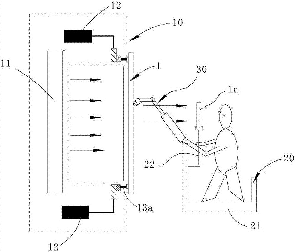
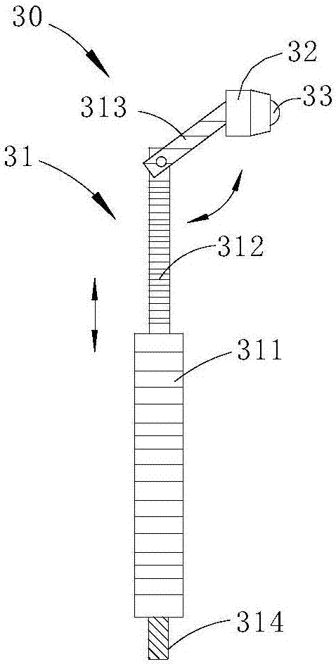
[0026] refer to figure 1 , the macro inspection device of the embodiment of the present invention includes a lighting module 10, a lifting module 20 and a pressing mechanism 30, wherein the lighting module 10 is used to simulate lighting a panel 1 without a TFT side polarizer; the lifting module 20 is installed on the lighting module at intervals 10 side, and can reciprocate in the vertical direction, and an operation panel for controlling the height of the lifting module 20 is provided inside; the pressing mechanism 30 is used to contact and press the substrate on the surface of the panel 1, so...


PUM


Abstract

The invention discloses a macroscopic inspection device and a macroscopic inspection method. The macroscopic inspection device comprises a lighting module, a lifting module and a pressing module, wherein the lighting module is used for simulating lighting of a panel without a TFT lateral polaroid, the lifting module is arranged at one side of the lighting module in a spaced mode, can move in the vertical direction and is internally provided with an operation panel used for controlling the height of the lifting module, and the pressing module is used for making contact with and pressing a substrate on the surface of the pressing panel so as to observe the surface of the substrate obtained after pressing. By putting the panel without the TFT lateral polaroid beside the lighting module and arranging the lifting module opposite to the panel, the TFT lateral polaroid and the pressing mechanism can move up and down along with the lifting module, after the lighting module is started, the substrate can be subjected to macroscopic inspection by penetrating the TFT lateral polaroid, by pressing different parts of the substrate through the pressing mechanism, detection can be effectively conducted on an alignment anomaly caused by HVA optical alignment, the phenomenon that the HVA alignment anomaly leaks to secondary lighting to cause a lot of scraps is avoided, and therefore the product yield is increased, and the production line stability is improved.

Description

technical field [0001] The invention relates to the technical field of panel manufacturing, in particular to a macroscopic inspection device and a macroscopic inspection method. Background technique [0002] HVA optical alignment technology is a kind of liquid crystal alignment technology in the production process of TFT LCD (Thin Film Transistor Liquid Crystal Display, thin film transistor liquid crystal display) liquid crystal panel. , and then through UV (Ultra-Violet Ray, ie ultraviolet) light irradiation to make the polymer monomers in the substrate react, so as to achieve the purpose of liquid crystal alignment, a photo-alignment technology. Compared with traditional friction alignment, it has the advantages of high contrast, wide viewing angle, less static electricity and particles, and has gradually become the mainstream technology for large-size LCD panel production. [0003] In the production process of HVA photo-alignment products, after the secondary UV alignmen...

Claims


Application Information

Patent Timeline
IPC IPC(8): G02F1/13G02F1/1337G01N21/88G01N21/95
CPCG02F1/1309G01N21/8803G01N21/95G01N2021/9513G02F1/1337
Inventor 刘小成尹凤鸣肖松
Owner SHENZHEN CHINA STAR OPTOELECTRONICS TECH CO LTD
Learn More