Vacuum oil injection system for transformer or capacitor

A capacitor and transformer technology, applied in the field of transformer or capacitor vacuum oil injection system, can solve the problems of shortening the service life of chain materials, waste of transformer or capacitor oil, pollution, etc., and achieve the effect of improving safety performance, improving service life and ensuring transmission efficiency.

Active Publication Date: 2017-07-28
HEFEI GENERAL MACHINERY RES INST
View PDF4 Cites 6 Cited by
  • Summary
  • Abstract
  • Description
  • Claims
  • Application Information

AI Technical Summary

Problems solved by technology

The other is "oil tank type oil injection". The upper layer uses an oil injection tank and the lower layer uses an oil collection tank, which will cause a great waste of transformer or capacitor oil, and will also pollute the insulating oil injected into the capacitor.
The problem brought by the traditional oil filling method is that each oil injection requires a lot of insulating medium oil, which greatly increases the workload of oil treatment, and the insulating medium oil is prone to spilling when the tank is assembled, causing serious environmental pollution, especially Dirt on the outer surface of the capacitor and the inner wall of the load-bearing equipment is easy to enter the transformer or capacitor when the insulating medium is filled with oil, which will reduce the withstand voltage value of the transformer or capacitor film at high voltage, and seriously affect the internal quality and service life of the transformer or capacitor.
The problem exist

Method used


Image

  • Vacuum oil injection system for transformer or capacitor
  • Vacuum oil injection system for transformer or capacitor
  • Vacuum oil injection system for transformer or capacitor

Examples


Example Embodiment

[0037] Below in conjunction with embodiment technical solution of the present invention is made more specific description:

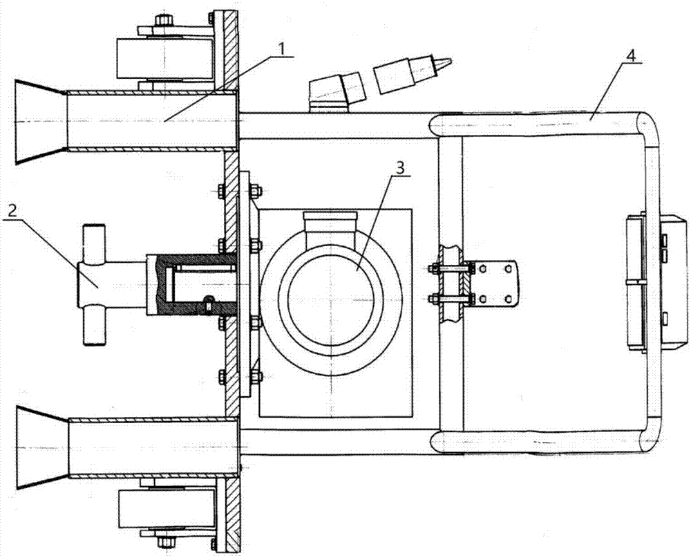
[0038] The vacuum oiling system of the present invention includes a tractor for transporting the transformer or capacitor 5 to be oiled and a vacuum oiling device for oiling the transformer or capacitor 5 to be oiled.

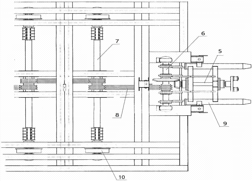
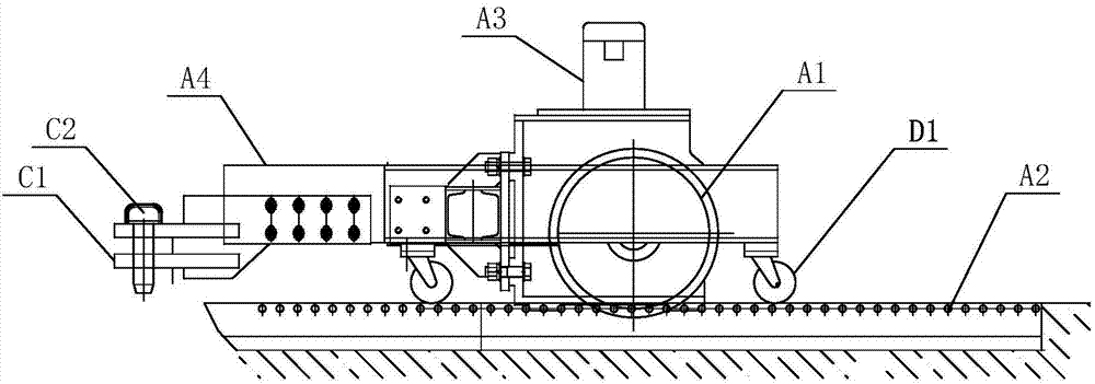
[0039] Wherein the structure of the tractor is as follows image 3 , 4 Shown:

[0040] The tractor includes a headstock A and a car body B that is detachably connected to the headstock A and is used to place the oil-filled transformer or capacitor 5. The headstock A is installed outside the vacuum tank 3 through a transmission sprocket A1. The chain rail A2 meshes to realize the reciprocating movement of the tractor.

[0041] A pair of the chain rails A2 are arranged in parallel on the ground, and the chain rails A2 are correspondingly engaged with the transmission sprockets A1 installed at both ends of the transmission shaft of the he...


PUM


Abstract

The invention relates to a vacuum oil injection system for a transformer or a capacitor. The vacuum oil injection system comprises a towing vehicle and a vacuum oil injection device. The vacuum oil injection device comprises an oil-level controller, an oil storage tank, a buffering tank and a vacuum tank; the oil storage tank supplements oil into the buffering tank, and relying on the liquid level difference, the buffering tank automatically injects oil into the transformer or the capacitor; the oil-level controller controls the oil storage tank to stop to supplement oil when the oil level in the buffering tank is located on the upper set liquid level, and controls the oil storage tank to start to supplement oil when the oil level in the buffering tank is located on the lower set liquid level, an oil injection soaking pipe communicated with the vacuum tank is installed on an oil injection opening of the transformer or the capacitor, and the maximum liquid level permitted in the oil injection soaking pipe is slightly higher than the upper set liquid level; the towing vehicle comprises a vehicle head and a vehicle body detachably connected with the vehicle head, and the vehicle head is engaged with chain rails installed outside the vacuum tank through transmission chain wheels for achieving reciprocating motion of the towing vehicle. By means of the vacuum oil injection system for the transformer or the capacitor, automatic oil supplementing and automatic oil injection of the transformer or the capacitor are achieved, and the towing vehicle is high in transmission efficiency and long in service life.

Description

technical field [0001] The invention relates to a transformer or capacitor vacuum oiling system. Background technique [0002] Vacuum oil filling is an effective measure to improve the insulation strength of transformers or capacitors. In order to maximize the penetration of insulating oil into the gaps in the internal components of transformers or capacitors and ensure that the amount of insulating oil inside the product is sufficient, the transformer or capacitor after oiling The height of the inner oil level must be accurate. The traditional oil filling method is: "immersion oil filling", that is, place a large storage tank in the vacuum tank, put the transformer or capacitor in the storage tank, put the insulating medium oil into the storage tank during oil filling, and let the transformer or capacitor Capacitors are filled with oil and impregnated in a storage tank filled with insulating medium oil. The other is "oil tank type oil injection". The upper layer uses an o...

Claims


Application Information

Patent Timeline
IPC IPC(8): H01F27/14H01G13/00B67D7/72
CPCB67D7/725H01F27/14H01G13/00
Inventor 张伟杨吉梅陈华锋汪雪涛张新建刘牧
Owner HEFEI GENERAL MACHINERY RES INST
Why Eureka
Try Eureka