
Dome valve for pneumatic conveying system and dome valve automatic control system

A technology of pneumatic conveying system and automatic control system, which is applied in the direction of valve details, valve devices, engine components, etc., can solve the problems of reduced sealing effect, high cost, and impact on use, and achieve the effects of avoiding wear, long life, and convenient replacement

Active Publication Date: 2017-08-01
ZHEJIANG GUTE PNEUMATIC MACHINERY
View PDF5 Cites 14 Cited by
  • Summary
  • Abstract
  • Description
  • Claims
  • Application Information

AI Technical Summary

Problems solved by technology

During the continuous opening and closing process of the dome valve, the surface of the dome valve plate will gradually wear and tear, resulting in a decrease in sealing performance and needs to be replaced; in the current dome valve, the valve body and the dome valve plate are fixed structures, once round When the top valve plate needs to be replaced, only the whole dome valve can be replaced, which is costly and labor-intensive
[0003] In addition, in the current dome valve structure, there is a gap between the hemispherical spool and the valve port, which can reduce or eliminate the wear on the contact surface between the hemispherical spool and the valve port. The sealing of the valve port in this structure is basically It is realized by sealing the airbag, but the airbag is also susceptible to friction on the surface of the valve core. Once the sealed airbag is damaged, the sealing effect will decrease and affect the use

Method used


Image

  • Dome valve for pneumatic conveying system and dome valve automatic control system
  • Dome valve for pneumatic conveying system and dome valve automatic control system
  • Dome valve for pneumatic conveying system and dome valve automatic control system

Examples


Embodiment Construction

[0024] The present invention will be further described in detail below in conjunction with the accompanying drawings and specific embodiments.

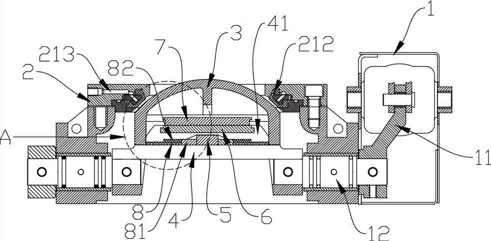
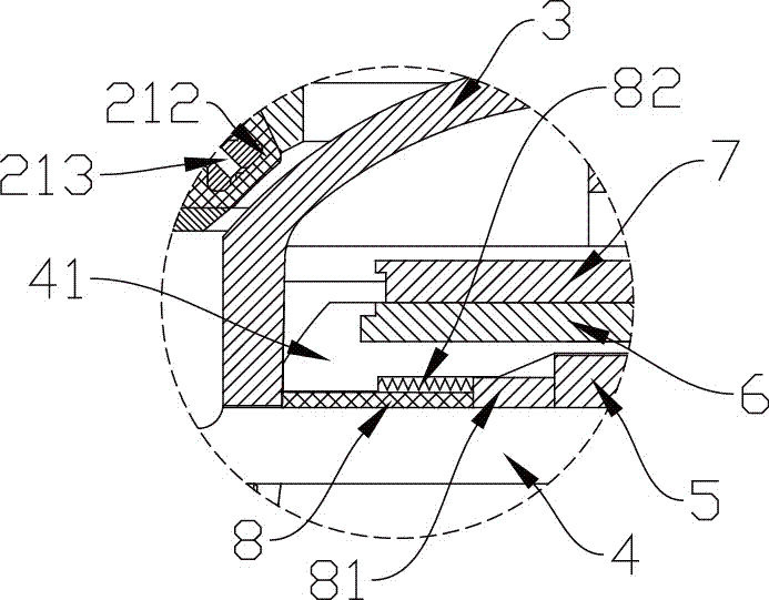
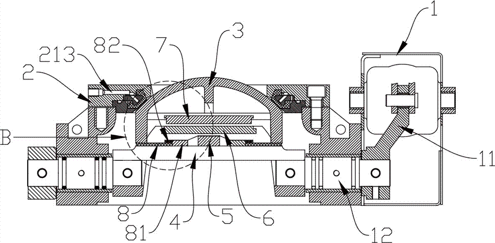
[0025] refer to figure 1 to Figure 6 , a dome valve used in a pneumatic conveying system, including a valve body 2, a hemispherical spool 3 arranged in the valve body 2, a driving arm 11 for driving the hemispherical spool 3 to rotate, and a driving arm 11 Connected pneumatic actuators, the valve body 2 includes an upper valve body 21 and a lower valve body 23 assembled together by bolts, the upper valve body 21 is provided with a valve port 211 and a sealing air bag 212, and the lower valve body 23 is provided with a valve core mounting seat 4, which is provided with a disc-shaped first electromagnet 6, and the hemispherical valve core 3 is provided with a disc repelling the first electromagnet 6. Shaped first magnet 7, the outer edge of the hemispherical valve core 3 is stuck on the protrusion 41 of the valve core mounting seat ...


PUM


Abstract

A dome valve for a pneumatic conveying system comprises a valve body, a semi-spherical valve element arranged in the valve body, a drive crank used for driving the semi-spherical valve element to rotate and a pneumatic executing element connected with the drive crank. The valve body comprises an upper valve body and a lower valve body which are assembled together. The upper valve body is provided with a valve opening and a seal air bag. The lower valve body is internally provided with a valve element installation seat. The dome valve has the beneficial effects that in the valve opening and closing process, the semi-spherical valve element does not make contact with the seal air bag or generate friction with the seal air bag during rotating, so that wear is avoided; and meanwhile, the semi-spherical valve element is long in service life and convenient to replace.

Description

technical field [0001] The invention belongs to the field of industrial valves, in particular to a dome valve used in a pneumatic conveying system, and also relates to an automatic control system for the dome valve. Background technique [0002] In the industrial field, especially in the field of pipeline medium transportation, industrial valves are widely used. Among them, the dome valve is widely used in the pneumatic ash conveying system of coal-fired power plants. It is generally composed of a valve body, a hemispherical valve core, a sealing air bag, and a driving crank arm. Turn to open to realize opening and closing of the valve. During the continuous opening and closing process of the dome valve, the surface of the dome valve plate will gradually wear and tear, resulting in a decrease in sealing performance, which needs to be replaced; in the current dome valve, the valve body and the dome valve plate are fixed structures. When the top valve plate needs to be repla...

Claims


Application Information

Patent Timeline
Patent Type & Authority Applications(China)
IPC IPC(8): F16K5/06F16K5/08F16K5/14F16K31/06F16K31/12F16K37/00
CPCF16K5/0605F16K5/0689F16K5/08F16K5/14F16K31/0675F16K31/12F16K37/0025
Inventor 张寿根肖翰叶建山
Owner ZHEJIANG GUTE PNEUMATIC MACHINERY
Learn More