Maglev control moment gyroscope monitoring system for simulating rocket launching and orbit operation

A technology for controlling torque gyroscopes and monitoring systems, which is applied in the field of magnetic suspension control torque gyro monitoring systems, can solve the problems of inability to simulate the real working conditions of the magnetic suspension control torque gyro, and the inability to detect, control and evaluate the performance of the magnetic suspension control torque gyro, so as to achieve detection and Comprehensive control, good real-time performance, and complex effects

Active Publication Date: 2017-08-01
重庆高孚透平科技有限公司
View PDF7 Cites 9 Cited by
  • Summary
  • Abstract
  • Description
  • Claims
  • Application Information

AI Technical Summary

Problems solved by technology

[0003] In the research and development and testing phase of the magnetic levitation control torque gyro on the ground, it is necessary to test various indicators in the two states of rocket launch and orbit operation to evaluate the performance of the magnetic levitation control torque gyroscope. The existing magnetic levitation control torque gyroscope adopts decentralized control , The magnetic bearing device, high-speed motor device, frame servo device and locking and unlocking device each have an independent control and communication system. The computer is used to control and detect the working status of each system independently, and it is impossible to detect the overall performance of the magnetic levitation control torque gyroscope. Control and evaluation, the maglev control moment gyroscope also communicates with the on-board computer as a whole when it is actually used, so the existing decentralized communication and control methods cannot simulate the real working conditions of the maglev control moment gyroscope

Method used


Image

  • Maglev control moment gyroscope monitoring system for simulating rocket launching and orbit operation
  • Maglev control moment gyroscope monitoring system for simulating rocket launching and orbit operation
  • Maglev control moment gyroscope monitoring system for simulating rocket launching and orbit operation

Examples


Embodiment Construction

[0090] The present invention will be further described in detail through the drawings and examples below. Through these descriptions, the features and advantages of the present invention will become more apparent.

[0091] The word "exemplary" is used exclusively herein to mean "serving as an example, embodiment, or illustration." Any embodiment described herein as "exemplary" is not necessarily to be construed as superior or better than other embodiments. While various aspects of the embodiments are shown in drawings, the drawings are not necessarily drawn to scale unless specifically indicated.

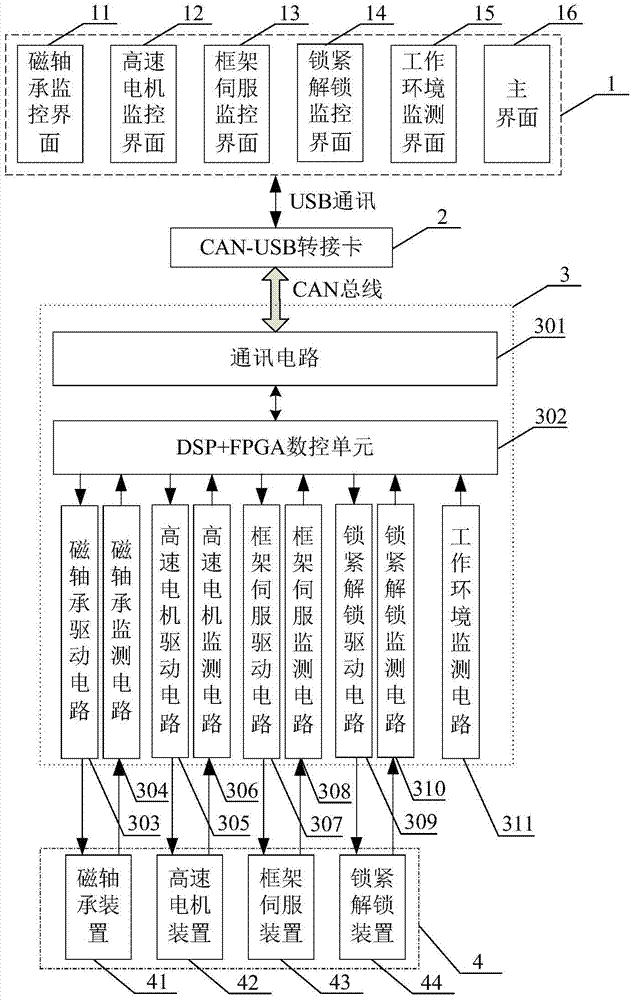
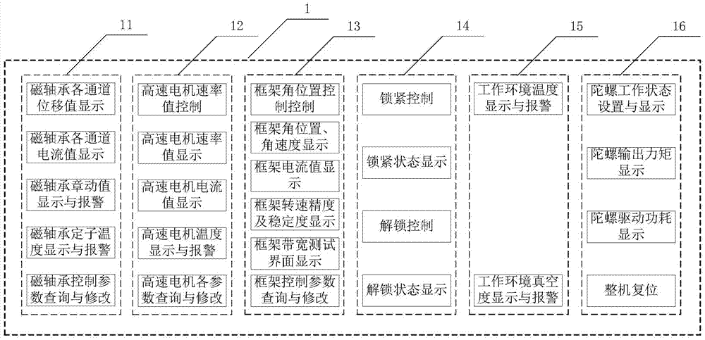
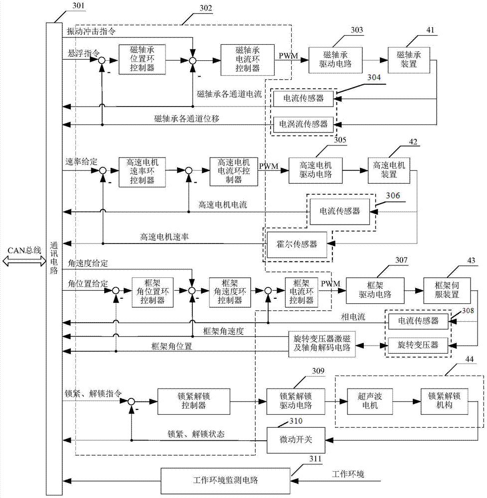
[0092] According to a kind of simulating rocket launch provided by the present invention and the maglev control moment gyro monitoring system of running in orbit, such as figure 1 As shown, the monitoring system includes a computer simulation setting and monitoring interface 1, a CAN-USB adapter card 2, a monitoring and communication circuit 3 and a magnetic levitation control tor...


PUM


Abstract

The invention discloses a maglev control moment gyroscope monitoring system for simulating rocket launching and orbit operation, which comprises a computer simulation setting and monitoring interface 1, a CAN-USB transfer card 2, a monitoring and communication circuit 3 and a maglev control moment gyroscope device 4, wherein the monitoring and communication circuit 3 comprises a communication circuit 301, a DSP+FPGA numerical control unit 302, a driving circuit and a detection circuit; and the DSP+FPGA numerical control unit 302, the driving circuit and the monitoring circuit form a closed loop control system to realize control and detection on the maglev control moment gyroscope device 4. The monitoring system of the invention can simulate the working conditions of the maglev control moment gyroscope device 4 at two stages of rocket launching and orbit operation; and through the CAN-USB transfer card 2, the computer simulation setting and monitoring interface 1 communicates with the monitoring and communication circuit 3, and integrated monitoring, analysis and control on the maglev control moment gyroscope device 4 can be carried out.

Description

technical field [0001] The invention relates to a magnetic levitation control moment gyro monitoring system, in particular to a magnetic levitation control moment gyro monitoring system for simulating rocket launch and in-orbit operation. Background technique [0002] The magnetic levitation control torque gyro adopts the bearing support method of magnetic levitation. Compared with the mechanical control torque gyro supported by the mechanical ball bearing, it avoids the wear of the mechanical bearing itself due to friction, so it has the advantages of long life, low vibration, high speed, etc. It is a large aerospace It is an important attitude control actuator on aircraft and space stations, and has broad application prospects. [0003] In the research and development and testing phase of the magnetic levitation control torque gyro on the ground, it is necessary to test various indicators in the two states of rocket launch and orbit operation to evaluate the performance of...

Claims


Application Information

Patent Timeline
Patent Type & Authority Applications(China)
IPC IPC(8): G05B19/042
CPCG05B19/0428G05B2219/25314
Inventor 徐向波张亚楠陈劭张俊梅
Owner 重庆高孚透平科技有限公司
Why Eureka
Try Eureka